SAE J1939 is a crucial communication standard for heavy-duty vehicles. Do you need a simple, yet comprehensive introduction to SAE J1939? This guide provides a practical overview of the J1939 protocol, including Parameter Group Numbers (PGNs), Suspect Parameter Numbers (SPNs), key characteristics, request messages, and the transport protocol. With real-life examples, you’ll learn how to decode raw J1939 data.
Download as PDF
What is J1939?
SAE J1939 is a set of standards that define how Electronic Control Units (ECUs) communicate via the Controller Area Network (CAN) bus in heavy-duty vehicles. While CAN bus provides the foundation for communication, J1939 provides the “language” for ECUs to communicate effectively. J1939, in technical terms, is a higher-layer protocol built upon the CAN bus.
J1939 provides a standardized method for communication across ECUs, fostering interoperability across manufacturers. While passenger cars often use proprietary OEM-specific protocols, J1939 offers a common language across manufacturers of heavy-duty vehicles. This standardization is critical for data logging applications across a variety of heavy-duty vehicles.
SAE International plays a vital role in the development and maintenance of the J1939 standard, ensuring it evolves to meet new challenges like vehicle electrification and the emergence of CAN FD.
4 Key Characteristics of J1939
The J1939 protocol is defined by a set of key characteristics:
250K/500K Baud Rate & 29-bit Extended ID
J1939 typically uses a baud rate of 250K, with recent support for 500K. The identifier is an extended 29-bit identifier (CAN 2.0B).
Broadcast + On-Request Data
While most J1939 messages are broadcast on the CAN bus, some data is only available upon request.
PGN Identifiers & SPN Parameters
J1939 messages are identified using 18-bit Parameter Group Numbers (PGNs). Individual data signals within a message are called Suspect Parameter Numbers (SPNs).
Multibyte Variables & Multi-Packets
Multibyte variables are sent with the least significant byte first (Intel byte order). The J1939 transport protocol supports PGNs with up to 1785 bytes.
Additional characteristics include:
- Reserved PGN Range: PGNs 00FF00 through 00FFFF are reserved for proprietary use.
- Special Values: A data byte of 0xFF (255) signifies N/A data, while 0xFE (254) indicates an error.
- Dynamic Addressing: J1939 uses an address claiming procedure to dynamically assign source addresses to ECUs via an 8-bit address after network initialization.
J1939 History
- 1985: SAE begins development of the J1939 protocol.
- 1994: Initial documents released (J1939-11, J1939-21, J1939-31).
- 2000: The first top-level document is published, and CAN is formally included.
- 2001: J1939 starts to replace SAE J1708/J1587.
- 2013: J1939 Digital Annex released, digitizing PGN/SPN data.
- 2020-21: J1939-17 and J1939-22 released (J1939 on CAN FD).
J1939 Future
Several trends are impacting the protocol’s future:
- Bandwidth Challenges: Increased bandwidth demands may lead to broader adoption of J1939-22 (J1939 on CAN FD), more J1939 networks per vehicle, or a shift towards Automotive Ethernet.
- Right to Repair: The ‘Right to Repair’ movement in heavy-duty vehicles is pushing for increased access to vehicle data, while OEMs are incentivized to offer closed J1939 telematics systems, potentially driving the use of more proprietary PGN/SPN encoding.
- J1939 EVs: Electric heavy-duty vehicles could pose a risk to J1939 standardization, due to the lack of emissions measurement requirements and the potential for OEM EV development to outpace standardized J1939 PGN/SPN encoding.
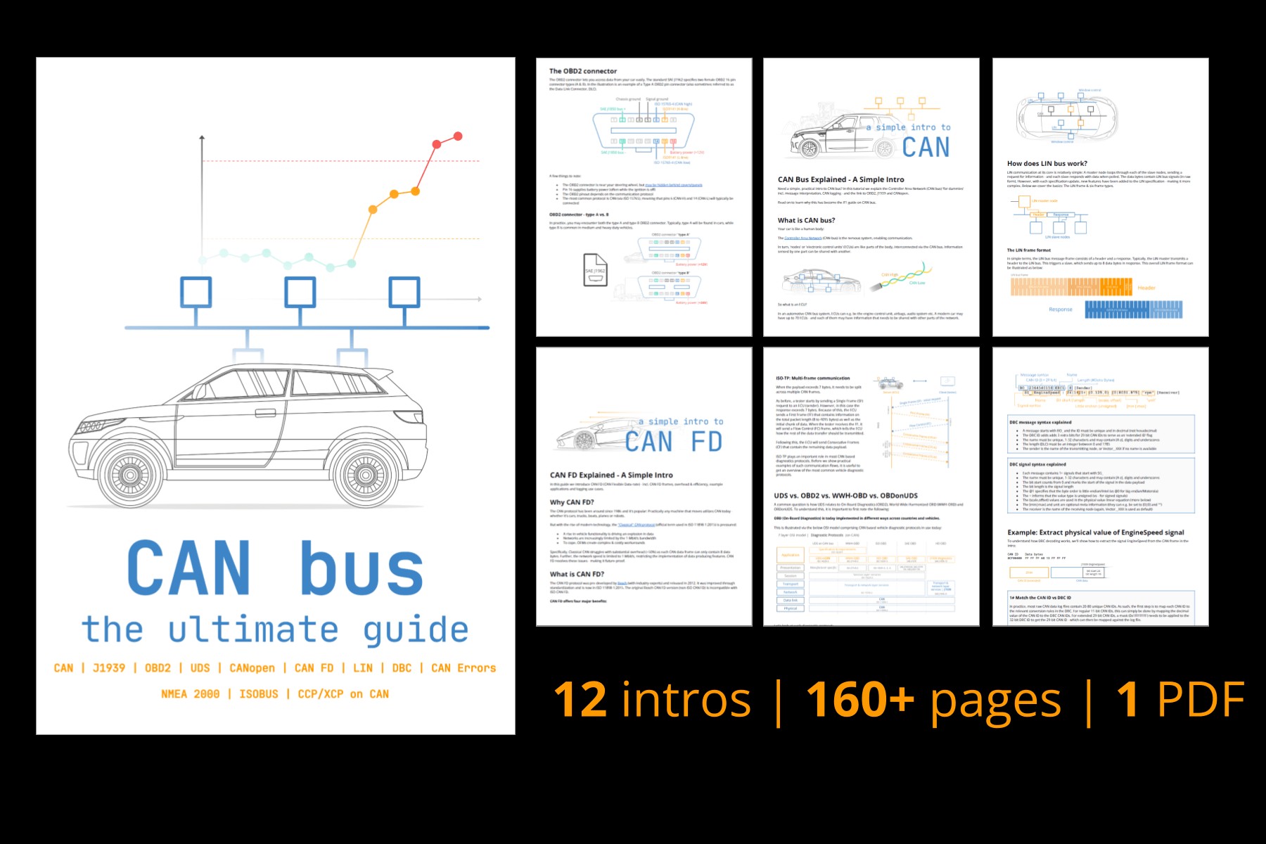
Get Our ‘Ultimate CAN Guide’
Want to become a CAN bus expert? Get our 12 ‘simple intros’ in one 160+ page PDF:
Download now
J1939 Standards (Higher-Layer Protocol)
J1939 builds upon the CAN bus, which specifies the physical layer (ISO 11898-2) and data link layer (ISO 11898-1) of the OSI model.
CAN provides the basic communication infrastructure, while J1939 adds a language for advanced communication. Other CAN-based protocols include OBD2, UDS, and CANopen.
The J1939 Connector [J1939-13]
The J1939-13 standard defines the “off-board diagnostic connector,” often called the J1939 connector or 9-pin Deutsch connector. This provides a standardized interface to the J1939 network on most heavy-duty vehicles.
The J1939 Deutsch connector provides access to the J1939 network through pins C (CAN high) and D (CAN low), simplifying interfacing with the J1939 network. However, some vehicles may offer access to a secondary J1939 network through pins F and G or pins H and J. Therefore, accessing the network via pins C and D may not grant access to all available J1939 data.
Other connectors may also be used, including:
- J1939 Backbone Connector: A 3-pin Deutsch connector for CAN H/L and CAN shield.
- CAT Connector: A grey 9-pin Deutsch connector with a different pin-out than the standard J1939 connector.
- OBD2 Type B Connector: In some heavy-duty vehicles, this provides direct access to the J1939 network through pins 6 and 14.
- Volvo 2013 OBD2 Connector: Similar to the Type B OBD2 connector but adds access to J1939 high via pin 3 and J1939 low via pin 11.
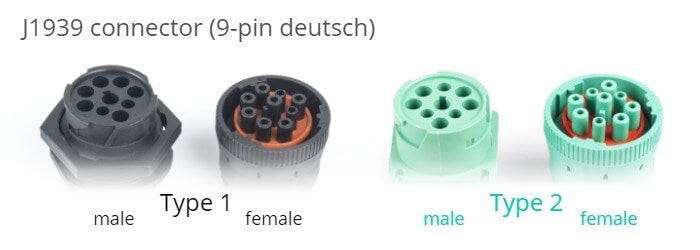
Black Type 1 vs Green Type 2
The J1939 Deutsch connector is available in two versions: the original black connector (Type 1) and the newer green connector (Type 2), introduced around 2013-14. Green Type 2 J1939 adapter cables are backward compatible and can be used with both black and green connectors.
J1939 type 2 female connectors are physically backward compatible, while Type 1 female connectors only fit Type 1 male sockets. Type 2 connectors support the SAE J1939-14 standard, which enables 500K bit rates. The physical block in Type 1 connectors prevents older hardware (presumably using 250K bit rates) from being connected to 500K bit rate J1939 networks.
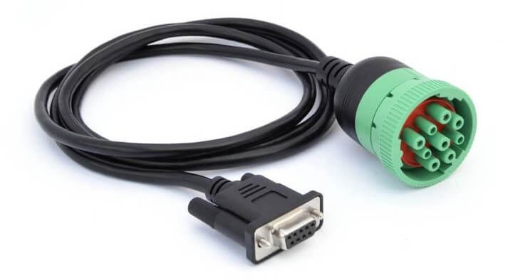
Below is an example of a DB9-J1939 adapter cable (type 2):
The J1939 PGN and SPN [J1939-21/71]
Parameter Group Number (PGN)
The J1939 PGN is an 18-bit subset of the 29-bit extended CAN ID, serving as the unique frame identifier within the J1939 standard. The rules for decoding raw J1939 data are specified at the PGN level, rather than the 29-bit ID level. Thus, multiple CAN messages with different CAN IDs can map to the same PGN and be interpreted identically.
Detailed Breakdown of the J1939 PGN
The 29-bit CAN ID consists of the Priority (3 bits), the J1939 PGN (18 bits), and the Source Address (8 bits). The PGN can be further divided into the Reserved Bit (1 bit), Data Page (1 bit), PDU format (8 bit), and PDU Specific (8 bit), where PDU represents Protocol Data Unit.
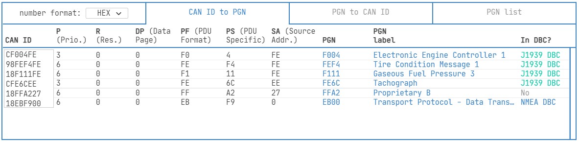
Tip: CAN ID to J1939 PGN Converter
Use our online J1939 PGN converter to convert 29-bit CAN IDs to J1939 PGNs and vice versa. The tool also checks if the J1939 PGN is included in our J1939 DBC file.
J1939 PGN converter
Understanding PDU1 vs. PDU2 PGNs is a common area of confusion. PDU2 PGNs make up approximately 95% of the PGNs in the J1939 Digital Annex. PDU2 messages are broadcast without a specific destination, while PDU1 messages are addressable and contain a destination address for targeting a specific node.
Suspect Parameter Number (SPN)
The J1939 SPN identifies the CAN signals (parameters) within the data payload. SPNs are grouped by PGNs and described by their bit start position, bit length, scale, offset, and unit. SPNs include examples like Engine Speed, Wheel Based Vehicle Speed, Fuel Level 1, and Engine Oil Temperature 2.
J1939 Digital Annex & J1939 DBC File
The J1939 Digital Annex (DA), introduced by SAE in 2013, is an Excel file that contains technical details on standard J1939 PGNs and SPNs. It only includes standardized PGNs/SPNs and excludes OEM-specific proprietary ones.
We convert the J1939 DA into a J1939 DBC file with over 1,800 PGNs and 10,000 SPNs. This conversion is updated quarterly with each new J1939 DA revision. The J1939 DBC file enables easy decoding of raw J1939 data in CAN software/API tools.
j1939 dbc intro
How to Decode Raw J1939 Data
Decoding J1939 data practically requires CAN software/API tools and a J1939 DBC file. However, understanding the underlying process is helpful.
Given a raw J1939 frame:
| CAN ID | Data bytes |
|---|---|
| 0x0CF00401 | 0xFF FF FF 68 13 FF FF FF |

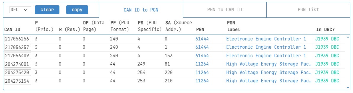
First, determine the J1939 PGN using a tool like our PGN converter. The CAN ID 0x0CF00401 translates to PGN 0xF004 (61444), also known as EEC1 (Electronic Engine Controller 1).
From the J1939 DA, EEC1 contains 8 SPNs, including Engine Speed.
To decode Engine Speed:
- Extract raw bits: Bytes 4 to 5, i.e., 0x6813.
- Use Intel byte order: Reverse to get 0x1368.
- Convert to decimal: 4968.
- Scale/offset: Multiply by 0.125 and offset by 0 to get 621 RPM.
J1939 Signal Ranges
J1939-71 specifies special interpretations for some signal values. If an ECU has a sensor error, the ‘error range’ can be used to communicate this. The J1939 DA specifies an ‘operational range’ for many signals, which is often more restrictive than the ‘valid range’. Our J1939 DBC file includes min/max values for all signals, using the operational range when available.
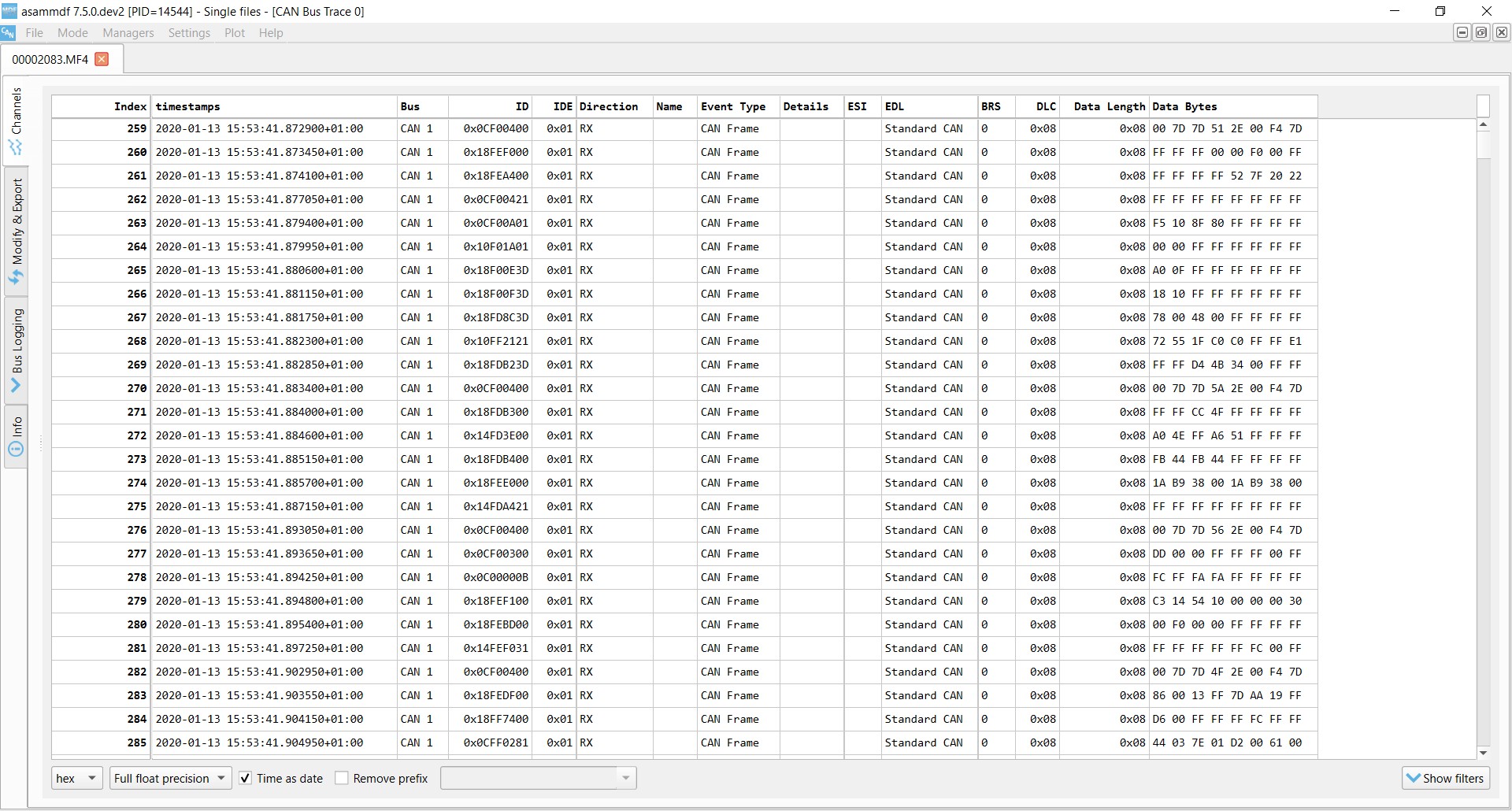
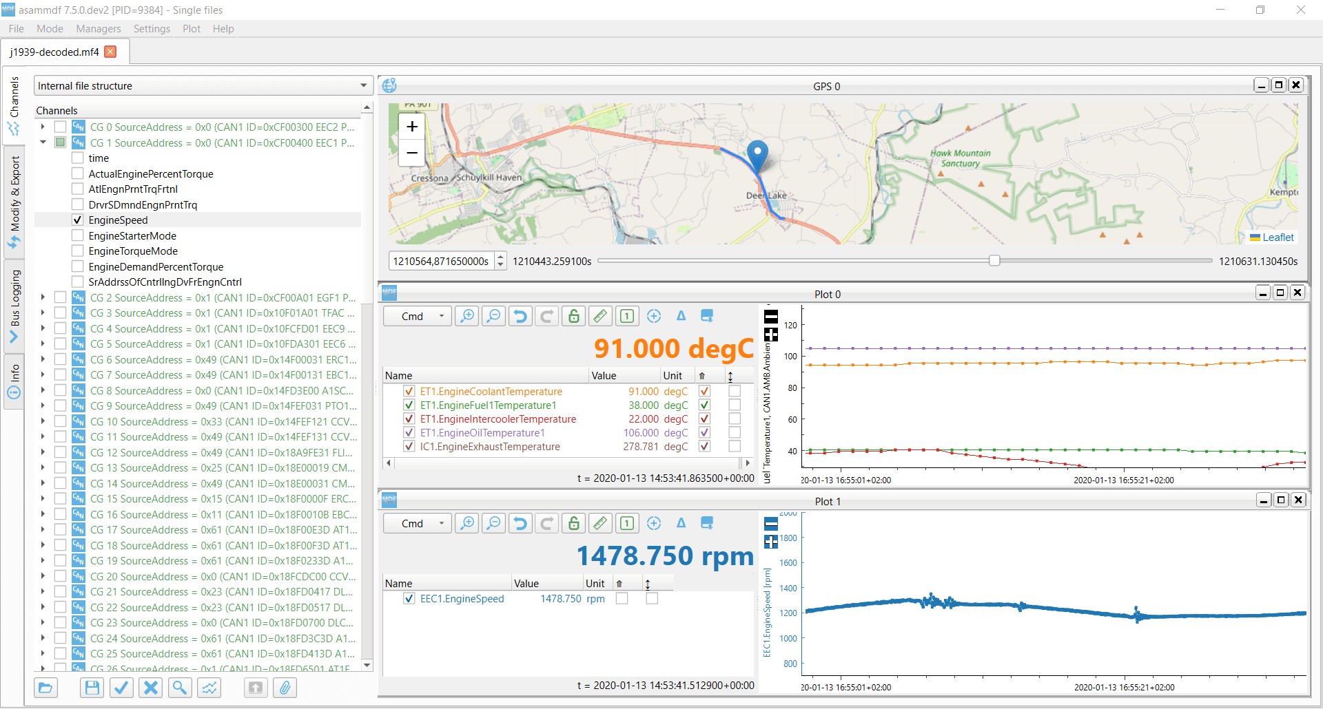
Example: J1939 Truck Data – Raw vs. Decoded
Raw J1939 data, consisting of timestamped 29-bit CAN IDs and 8-byte data payloads, can be filtered and searched, but cannot be plotted as time series.
Decoding raw J1939 data with a J1939 DBC file allows you to match CAN IDs and group SPNs by PGNs for analysis.
Request Message [J1939-21]
Most J1939 messages are transmitted periodically, but some are only transmitted upon request (e.g., by a diagnostic tool or J1939 data logger).
A common example is J1939 diagnostic messages like DM2, containing Diagnostic Trouble Codes (DTCs).
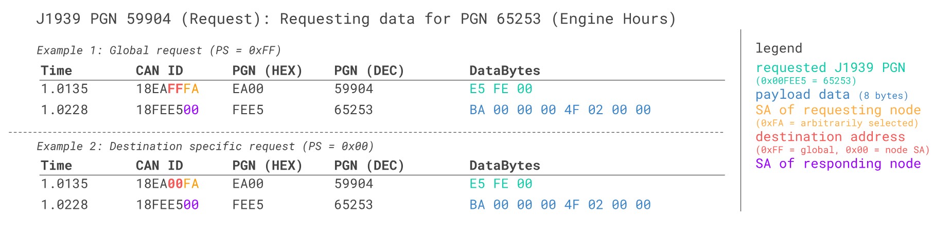
To send a J1939 request, a special “request message” (PGN 59904) is used with just 3 data bytes, containing the requested PGN in Intel byte order.
J1939 Transport Protocol (TP) [J1939-21]
Some message payloads exceed 8 bytes, requiring the data to be split across multiple CAN frames. J1939 specifies two transport protocols to achieve this:
Peer-to-Peer (RTS/CTS)
The transmitting node initiates a connection with a Request To Send (RTS) message. The receiver controls subsequent communication with Clear To Send (CTS) messages, ending with an End of Message Acknowledge (EoMA) message.
Broadcast (BAM)
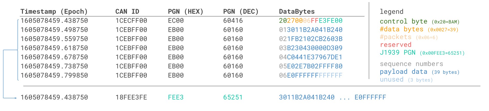
The transmitting node begins with a Broadcast Announce Message (BAM, PGN 0xEC00) followed by Data Transfer (DT, PGN 0xEB00) messages, without receiver control.
Example: J1939 BAM Transport Protocol incl. Reassembly
The J1939 transport protocol uses two PGNs:
- TP.CM: TP – Connection Management (0xEC00)
- TP.DT: TP – Data Transfer (0xEB00)
The TP.CM payload contains a control byte that varies based on the message type (0x20 for BAM), along with the number of data bytes and packets and the PGN of the multi-packet message (Intel byte order). The TP.DT message uses the 1st byte as a sequence counter (1 to 255), and the remaining 7 bytes contain the segmented data payload. A single J1939 TP sequence can carry up to 7 x 255 = 1785 data bytes.
J1939 Data Logging – Example Use Cases
Several common use cases exist for recording J1939 data:
Heavy Duty Fleet Telematics
J1939 data can be used in fleet management to reduce costs and improve safety.
j1939 telematics
Live Stream Diagnostics
Technicians can perform real-time J1939 diagnostics by streaming decoded J1939 data to a PC.
j1939 streaming
Predictive Maintenance
Vehicles can be monitored via WiFi CAN loggers in the cloud to predict breakdowns.
predictive maintenance
Heavy-Duty Vehicle Blackbox
A CAN logger can serve as a “blackbox” for heavy-duty vehicles, providing data for disputes and J1939 diagnostics.
can bus blackbox
Do you have a J1939 data logging use case? Reach out for free sparring!
Contact us
For more introductions, see our guides section or download the ‘Ultimate Guide’ PDF.
Need to log/stream J1939 data?
Get your CAN logger today!
Buy now
Contact us
Recommended for You
J1939 VEHICLE TELEMATICS
MINING TELEMATICS & DASHBOARDS
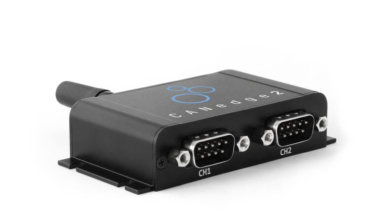
CANEDGE2 – PRO CAN IoT LOGGER