Category 6 Ethernet cables, commonly known as Cat6, are the backbone of modern network infrastructure in both homes and businesses. Renowned for their stability and reliability, Cat6 cables are essential for high-speed data transfer. Just like their predecessors, Cat6 cable termination relies on specific wiring diagrams, namely the A and B standards. This comprehensive guide delves into the intricacies of Cat6 wiring, providing a detailed Cat6 wiring diagram, step-by-step instructions on Cat6 cable termination, and valuable tips to ensure a successful network setup.
Understanding Cat6 Cables
Introduced by the Telecommunications Industry Association (TIA) in 2002, Category 6 (Cat6) cable is a high-performance twisted pair cable standard used for Ethernet and other network physical layers. Cat6 cables are extensively deployed in Local Area Networks (LANs) and Wide Area Networks (WANs), serving as crucial connections between computers, routers, switches, printers, scanners, hubs, and various other network devices. A standard unshielded Cat6 cable comprises four twisted pairs of wires, a rip cord for easy jacket removal, and a spline that separates these pairs to minimize crosstalk. For environments with electromagnetic interference (EMI) or radio frequency interference (RFI), shielded Cat6 cables are available, featuring additional layers of shielding for enhanced signal protection.
Cat6 cables are further categorized based on their construction and jacket ratings. Solid Cat6 cables utilize solid copper wires, typically preferred for permanent installations, while stranded Cat6 cables, with their flexible stranded copper wires, are better suited for patch cables and frequent movement. Depending on the cable jacket material, Cat6 cables are classified as CM (general purpose), CMR (riser-rated for vertical runs), and CMP (plenum-rated for air-handling spaces), each designed for specific installation environments and fire safety requirements. Cat6 cables offer superior performance compared to older standards like Cat5e and Cat5, supporting higher bandwidth and faster data transfer rates, making them ideal for demanding network applications.
Cat6 cables are designed to be terminated with RJ45 connectors. To maximize the performance capabilities of Cat6 cables, it is highly recommended to use Cat6-rated connectors. For shielded Cat6 cables, shielded Cat6 connectors are necessary to maintain the shielding effectiveness throughout the connection. However, Cat6 cables maintain backward compatibility with Cat5 and Cat5e connectors, offering flexibility in various networking scenarios.
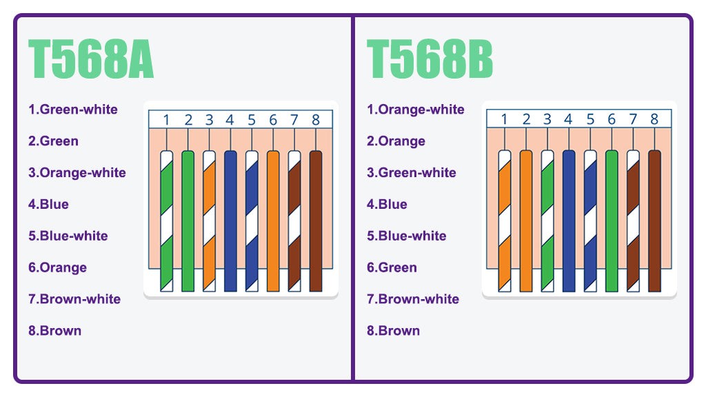
Decoding the Cat6 Wiring Diagram
A Cat6 wiring diagram is a visual representation of the wire arrangement sequence required when terminating Cat6 cables. Adhering to the correct Cat6 cable diagram is paramount to prevent connectivity problems and ensure optimal network performance.
Two primary wiring standards exist for Category 6 cables: T568A and T568B. The key difference between them lies in the swapped positions of the green and orange wire pairs. In most standard network applications, the choice between T568A and T568B Cat6 wiring color codes is largely preferential; the crucial aspect is consistency. Select either standard and maintain it throughout your entire network installation. In practice, the T568B wiring diagram is more commonly used for Cat6 cable termination in commercial and residential settings.
Another critical consideration for the Cat6 wiring diagram is maintaining consistent color sequencing at both ends of the cable. Employing the same wiring standard (either T568A or T568B) at both termination points is essential for standard “straight-through” network cables. Using T568A on one end and T568B on the other creates a crossover cable, which is designed for specific network configurations, primarily for direct device-to-device connections without a switch or hub, though less common in modern networks.
Selecting the Right Cat6 Wiring Diagram: T568A or T568B?
Choosing between the T568A and T568B wiring diagrams for your Cat6 installation depends on several factors:
- Legacy Compatibility (T568A): ANSI/TIA previously recommended T568A for residential installations due to its backward compatibility with older telecommunications technologies like analog phone lines and fax machines that utilized pin pairings differently. If your Cat6 network needs to interface with such legacy devices, T568A might be considered.
- Modern Network Standard (T568B): The vast majority of contemporary network equipment is designed and manufactured to utilize the T568B color code. For most standard network deployments involving modern routers, switches, computers, and peripherals, T568B is the more prevalent and often recommended choice.
- Existing Infrastructure Consistency: If you are expanding or modifying an existing network, it is crucial to identify the wiring standard already in use. Maintaining consistency with the existing wiring diagram is paramount to avoid compatibility issues and ensure seamless network integration. Use a cable tester to check existing terminations if unsure.
- Straight-Through vs. Crossover Cables: Historically, crossover cables (T568A on one end, T568B on the other) were necessary to connect two identical network devices directly (e.g., computer-to-computer). However, modern network devices now commonly feature Auto-MDIX (Medium Dependent Interface Crossover) technology. This intelligent feature automatically detects the required cable type, eliminating the need for crossover cables in most scenarios. Consequently, straight-through cables, wired with the same standard (typically T568B) at both ends, are suitable for almost all modern network connections.
Step-by-Step Guide: Terminating a Cat6 Cable
Once you’ve grasped the Cat6 wiring diagram and chosen your standard (we’ll use T568B for this tutorial), the next step is learning the practical process of Cat6 Ethernet cable termination. Here’s a detailed, step-by-step guide to help you successfully terminate Cat6 cables:
Preparation: Before commencing the termination process, gather all the necessary tools and materials. Having everything readily available will streamline the process and minimize interruptions.
- Pass-through Cat6 RJ45 Connectors: These connectors simplify the termination process, especially for beginners. The pass-through design allows wires to extend through the connector, making wire sequence verification and crimping easier and reducing wiring errors.
- Strain Relief Boots: These protective boots are highly recommended. They slide over the RJ45 connector and cable, providing protection against dust, physical stress, and damage at the cable-connector joint, extending the lifespan and reliability of the termination.
- Pass-through RJ45 Crimping Tool: A specialized crimping tool designed for pass-through RJ45 connectors is essential. These tools ensure a secure and reliable crimp, simultaneously cutting off the excess wires extending through the connector.
- Mini Wire Stripper: This tool is used to precisely remove the outer jacket of the Cat6 cable without damaging the inner wires. Choose a stripper with an adjustable blade to accommodate different cable types and prevent accidental nicking of the conductors.
- Cable Snips or Wire Cutters: These are used to neatly cut the rip cord, center spline, and the copper wires themselves to the correct length for insertion into the RJ45 connector. Sharp, precise snips are crucial for clean cuts.
- Network Cable Tester: A network tester is an invaluable tool for verifying the continuity and correct wiring of your terminated cable. It confirms that all wires are properly connected and in the correct sequence, saving troubleshooting time and ensuring a functional network connection.
Step 1: Slide on the Strain Relief Boot: Before attaching the RJ45 connector, slide the strain relief boot onto the Cat6 cable. Ensure the boot’s orientation is correct (wider opening facing the connector end). This step is often overlooked but crucial for cable protection and strain relief.
Step 2: Strip the Cable Jacket: Using the mini wire stripper, carefully remove approximately 1 inch of the outer cable jacket. Adjust the stripping blade depth to avoid damaging the insulation of the inner copper wires. Discard the stripped jacket piece.
Step 3: Trim the Rip Cord and Spline: Locate the rip cord (usually a thin nylon string) and the center spline (plastic divider) inside the cable. Use cable snips to cut and remove both the rip cord and the spline as close to the jacket edge as possible. These components are used during cable manufacturing and are no longer needed.
Step 4: Untwist and Straighten the Wires: Carefully untwist each of the four twisted pairs of wires. Separate the eight individual wires and straighten them as much as possible. Straightening the wires makes them easier to arrange in the correct order and insert into the RJ45 connector. Using the stripped jacket as a guide can aid in straightening.
Step 5: Arrange Wires in T568B Order: Following the T568B wiring standard, arrange the wires in the correct sequence: Orange-white, Orange, Green-white, Blue, Blue-white, Green, Brown-white, Brown. Ensure the wires are aligned neatly and in the correct order. Double-check the color sequence against the T568B diagram.
Step 6: Trim the Wires Evenly: Using cable snips, trim the straightened and arranged wires to create a clean, even cut. An angled cut can sometimes facilitate easier insertion into the RJ45 connector, but a straight cut is also acceptable. Cut the wires to a length that will allow them to fully insert into the RJ45 connector and reach the end contacts – typically around 1/2 inch from the jacket end.
Step 7: Insert Wires into RJ45 Connector: Carefully insert the arranged and trimmed wires into the pass-through RJ45 connector. Ensure each wire is inserted into the correct channel according to the T568B sequence. With pass-through connectors, the wires will extend out the front of the connector. Visually verify that the wire order is correct through the connector before proceeding.
Step 8: Verify Wire Sequence and Boot Placement: Double-check the wire sequence once more, ensuring it adheres to the T568B standard and that each wire is fully inserted into its designated pin position within the RJ45 connector. Slide the strain relief boot forward so it is positioned just behind the RJ45 connector, ready to be crimped into place.
Step 9: Prepare for Crimping: Before crimping, you can gently twist the excess wires extending through the front of the RJ45 connector. This helps to keep them together and makes insertion into the crimping tool cavity easier. This step is optional but can aid in a cleaner crimp.
Step 10: Crimp the RJ45 Connector: Insert the RJ45 connector with the cable into the pass-through RJ45 crimping tool. Ensure the connector is fully seated in the crimper. Firmly squeeze the crimping tool handles until they ratchet fully and release. This action crimps the connector pins, securing the wires and simultaneously cutting off the excess wires at the front of the connector in the case of a pass-through tool.
Step 11: Repeat for the Other End: Repeat steps 1 through 10 for the other end of the Cat6 cable. It is crucial to use the same wiring diagram (T568B in this example) at both ends to create a straight-through cable suitable for most network connections.
Step 12: Test the Cable: The final and essential step is to test the terminated Cat6 Ethernet cable using a network cable tester. Connect one end of the cable to the main unit and the other end to the remote unit of the tester. Activate the tester to check for continuity and correct wire mapping. The tester will indicate if all wires are correctly connected and in the right order. A successful test confirms a properly terminated and functional Cat6 cable.
Common Pitfalls in Cat6 Wiring
Cat6 cable termination can sometimes present challenges, particularly for those new to the process. Common issues include:
- Poor Pin Contact: If the copper wires are not fully inserted into the RJ45 connector or if the crimping is insufficient, the connector pins may not make proper contact with the wire conductors. This results in a faulty connection. Re-termination with a new connector is usually necessary in such cases.
- Incorrect Wire Sequence: Deviating from the chosen wiring diagram (T568A or T568B) leads to improper wire mapping and network connectivity issues. Double-checking the wire order before crimping is crucial.
- Jacket Not Crimped: Ensure the cable jacket is inserted far enough into the RJ45 connector to be secured by the crimp. This provides strain relief and a more robust termination.
For field terminations or situations where re-termination might be needed, field termination plugs (also known as tool-less connectors) are a convenient option. These connectors are designed for repeated use and often simplify the termination process in the field.
In environments with high levels of electromagnetic interference, using shielded Cat6 cables and shielded connectors is highly recommended. This combination provides enhanced protection against EMI and RFI, ensuring signal integrity and reliable network performance. Always use quality cables and connectors, adhere to correct termination practices, and keep cable runs within the maximum recommended length of 100 meters (328 feet) to achieve optimal and dependable network speeds.
Conclusion: Mastering Cat6 Wiring
Understanding and correctly applying Cat6 wiring diagrams is fundamental to building reliable Ethernet networks. Cat6 cables are the recommended standard for both home and office network deployments, offering a balance of performance and cost-effectiveness. By mastering the principles of Cat6 wiring and following the step-by-step termination guide, even beginners can confidently create Cat6 patch cables and build robust network connections. Proper Cat6 cable termination is a valuable skill for anyone involved in network installation and maintenance.
Frequently Asked Questions (FAQs)
Does a Cat6 cable utilize all eight wires?
Yes, Cat6 cables are designed for Gigabit Ethernet and utilize all eight wires for optimal performance. Pairs 1 and 2 are used for data transmission and reception, while pairs 3 and 4 are used for additional data transmission and Power over Ethernet (PoE) applications. This full utilization of all eight wires enables the high bandwidth and data transfer rates associated with Cat6 networks.
Is it safe to run Cat6 cables in the same conduit as electrical wires?
Running Cat6 cables alongside electrical wires in the same conduit is generally not recommended, especially for unshielded Cat6 cables. While Cat6 cables can be run parallel to low-voltage cables, unshielded Cat6 cables should be kept at least 30 cm (approximately 1 foot) away from power lines to minimize the risk of electromagnetic interference (EMI). If running Cat6 cables and electrical wires in close proximity is unavoidable, shielded Cat6 cables and conduits with sufficient barriers should be used to provide separation and reduce interference. Always consult local electrical codes and best practices.
What are the consequences of incorrect Cat6 cable wiring?
Incorrect wiring of Cat6 cables can lead to a range of network problems. These can include complete network failure (no connectivity), significantly reduced network speeds, data transmission errors, packet loss, and intermittent connections. Inconsistent wiring can also impact Power over Ethernet (PoE) functionality. Testing cables after termination is crucial to identify and rectify any wiring errors before network deployment, preventing potential downtime and performance issues.