SkyCiv has launched a free wind load calculator incorporating several code references, notably the ASCE 7-10 wind load procedure. In this guide, we will demonstrate how to calculate wind loads using an S3D warehouse model as an example:
Figure 1. Example warehouse model in SkyCiv S3D for wind load analysis.
Figure 2. Project site location in Cordova, Memphis, Tennessee (via Google Maps).
Table 1. Essential building data for wind load calculation.
| Location | Cordova, Memphis, Tennessee |
|---|---|
| Occupancy | Miscellaneous – Plant Structure |
| Terrain | Flat farmland |
| Dimensions | 64 ft × 104 ft in plan |
| Eave height of 30 ft | |
| Apex height at elev. 36 ft | |
| Roof slope 3:16 (10.62°) | |
| With openings | |
| Cladding | Purlins spaced at 2ft |
| Wall studs spaced at 2ft |
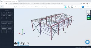

In this wind load example, we will determine the design wind pressures for a large, three-story plant structure. Figure 1 illustrates the building’s dimensions and framing, while Table 1 summarizes the relevant building data.
While numerous software solutions integrate wind load calculations into their design and analysis capabilities, few offer a detailed breakdown of this specific load type. Engineers often need to perform manual calculations to validate software results, ensuring accuracy and code compliance. This guide aims to clarify the process and provide a step-by-step approach to wind load calculations according to ASCE 7-10.
Wind Load Calculation Formulas per ASCE 7-10
The fundamental formulas for determining design wind pressure, as per ASCE 7-10, are outlined below.
For enclosed and partially enclosed buildings, the design wind pressure (p) is given by:
(p = qG{C}_{p} -{q}_{i}({GC}_{pi})) (1)
For open buildings, the formula is:
(p = q{G}_{f}{C}_{p} -{q}({GC}_{pi})) (2)
Where the parameters are defined as follows:
(G) = Gust Effect Factor: Accounts for the dynamic effects of wind gusts.
({C}_{p}) = External Pressure Coefficient: Represents the pressure distribution on the building’s exterior surfaces.
(({GC}_{pi})) = Internal Pressure Coefficient: Considers the pressure inside the building due to openings.
(q) = Velocity Pressure: The kinetic pressure of the wind at a specific height, calculated using the formula:
(q = 0.00256{K}_{z}{K}_{zt}{K}_{d}V^2) (3)
In this formula, velocity pressure ((q)) varies depending on the building surface:
- (q = {q}_{h}) for leeward walls, side walls, and roofs, evaluated at the mean roof height, (h).
- (q = {q}_{z}) for windward walls, evaluated at height, (z).
- ({q}_{i}) = ({q}_{h}) for negative internal pressure (((-{GC}_{pi}))) evaluation and ({q}_{z}) for positive internal pressure evaluation (((+{GC}_{pi}))) in partially enclosed buildings. For conservative design, ({q}_{i}) can be taken as ({q}_{h}).
The remaining parameters in the velocity pressure formula are:
({K}_{z}) = Velocity Pressure Coefficient: Varies with height and exposure category, reflecting the change in wind speed with altitude.
({K}_{zt}) = Topographic Factor: Accounts for wind speed-up effects due to topography (hills, escarpments).
({K}_{d}) = Wind Directionality Factor: Reduces wind loads based on the probability of maximum wind coming from any given direction.
(V) = Basic Wind Speed: The 3-second gust wind speed at 33 ft above ground in Exposure C, with a 50-year recurrence interval (mph).
This guide will delve into each parameter in detail, utilizing the Directional Procedure outlined in Chapter 30 of ASCE 7-10 to calculate design wind pressures for our example warehouse structure.
Detailed Parameter Explanation for ASCE 7-10 Wind Load Calculation
Risk Category Determination
The initial step in wind load calculation is to determine the Risk Category of the structure. This classification, based on the building’s occupancy and use, is crucial as it influences several factors in the wind load calculation process, including the basic wind speed and importance factor. For our plant structure example, given its industrial nature and potential consequences of failure, it falls under Risk Category IV. Refer to Table 1.5-1 of ASCE 7-10 for comprehensive details on risk category classifications.
Basic Wind Speed (V)
Basic wind speed (V) is a fundamental parameter representing the intensity of wind for a specific location. ASCE 7-10 provides wind speed maps (Figures 26.5-1A to 1C) that delineate basic wind speeds across the United States. These maps are categorized by risk category, ensuring appropriate wind speed values are used based on the structure’s importance and occupancy. The International Building Code (IBC) also defines and classifies Occupancy Categories, which often align with ASCE 7-10 Risk Categories.
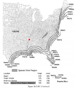
When using the ASCE 7-10 wind maps, select the map corresponding to the highest Risk Category applicable to your structure. In our Cordova, Memphis, Tennessee example, Figure 26.5-1B indicates a basic wind speed (V) of 120 mph (refer to Figure 3, red dot approximation). Note that for locations between wind contours, interpolation may be necessary to obtain a precise basic wind speed value.
Figure 3. Basic wind speed map excerpt from ASCE 7-10.
SkyCiv offers automated wind speed calculations within its Free Wind Tool, simplifying this step by requiring only location parameters.
Exposure Category Assessment
Exposure category is a crucial site-specific parameter that accounts for the roughness of terrain upwind of the structure. It significantly influences the velocity pressure coefficient (({K}_{z})) and consequently, the design wind loads. Section 26.7 of ASCE 7-10 details the procedure for determining exposure category.
The exposure category is determined based on the upwind terrain within a 45° sector for each wind direction considered. The exposure that yields the highest wind loads for a given direction should be conservatively adopted for design. ASCE 7-10 defines three main exposure categories: B, C, and D, with Exposure B representing the most sheltered and Exposure D the most exposed conditions.
Sections 26.7.2 and 26.7.3 provide detailed descriptions of each exposure classification. Table 2 below provides illustrative examples to further clarify the characteristics of each category.
Table 2. Examples of terrain classifications for Exposure Categories (Chapter C26 of ASCE 7-10 Commentary).
| Exposure | Example Terrain Description