Linear guide rails are crucial components in various mechanical systems, enabling smooth and precise linear motion. Understanding their construction, load capacity, rigidity, and applications is essential for effective design and implementation. This guide delves into the intricacies of linear guide rails, offering insights into their advantages and performance characteristics.
Understanding Load Capacity in Linear Guide Rails
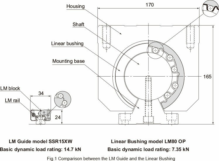
Linear motion (LM) Guides are designed with raceway grooves featuring a radius nearly identical to the ball radius, setting them apart from linear bushings. This design difference significantly impacts the permissible load and overall size of the guide. As illustrated in the image below, an LM Guide with a similar basic dynamic load rating is considerably smaller than a linear bushing, allowing for more compact designs.
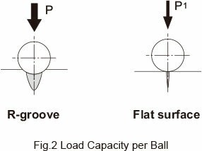
The space-saving advantage of LM Guides stems from the substantial difference in permissible load between the R-groove contact structure and the surface contact structure. The R-groove contact structure, with a radius approximately 52% of the ball radius, can withstand a load per ball that is 13 times greater than that of a surface contact structure. Given that service life is proportional to the cube of the permissible load, this enhanced ball-bearing load extends the service life by approximately 2,200 times compared to a linear bushing.
The table below illustrates the load capacity per ball for both R-groove and flat surface contact structures:
| Ball Diameter | R-groove (P) | Flat surface (P1) | P/P1 |
|---|---|---|---|
| φ 3.175(1/8″) | 0.90 kN | 0.07 kN | 13 |
| φ 4.763(3/16″) | 2.03 kN | 0.16 kN | 13 |
| φ 6.350(1/4″) | 3.61 kN | 0.28 kN | 13 |
| φ 7.938(5/16″) | 5.64 kN | 0.44 kN | 13 |
| φ 11.906(15/32″) | 12.68 kN | 0.98 kN | 13 |
This table clearly indicates the superior load-bearing capability of the R-groove design, contributing to the extended service life and compact design of LM Guides. The permissible contact surface pressure used in these calculations is 4,200 MPa.
High Rigidity of Linear Guide Rails
Linear guide rails excel in bearing both vertical and horizontal loads. Their circular-arc groove design enables them to handle preload effectively, further enhancing their rigidity. Preload is the load applied to a bearing before it is put into service, which helps to eliminate play and increase stiffness.
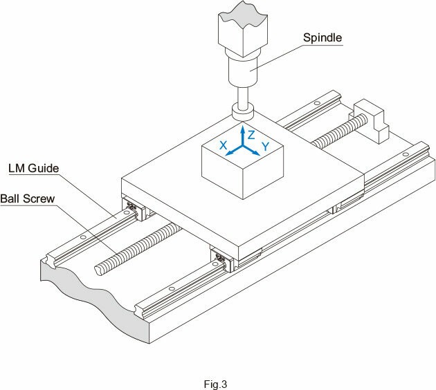
Compared to feed screw shaft systems and spindles, guide surfaces incorporating LM Guides demonstrate superior rigidity. The following example illustrates a comparison of static rigidity between an LM Guide, a feed screw shaft system, and a spindle:
Components:
- LM Guide: SVR45LC/C0 (C0 clearance: preload = 11.11kN)
- Ball Screw: BNFN4010-5/G0 (G0 clearance: preload = 2.64kN)
- Spindle: General-purpose cutting spindle
Table: Comparison of Static Rigidity (Unit: N/μm)
| Components | X-axis direction | Y-axis direction | Z-axis direction |
|---|---|---|---|
| LM Guide | – | 2400 | 9400 (radial) 7400 (reverse radial) |
| Ball screw | 330 | – | – |
| Spindle | 250 | 250 | 280 |
Note: The rigidity of the feed screw shaft system includes the rigidity of the shaft end support bearing.
This comparison highlights the exceptional rigidity of LM Guides, particularly in the Y and Z axes, making them ideal for applications requiring high precision and stability. This superior rigidity translates to improved performance and accuracy in various machining and automation processes.
Conclusion
Linear guide rails are essential for achieving precise and reliable linear motion in a wide range of applications. Their superior load capacity and high rigidity, stemming from their unique design and material properties, make them a preferred choice over traditional linear bushings and other motion systems. By understanding how to effectively utilize linear guide rails, engineers and designers can optimize the performance and longevity of their mechanical systems. Whether it’s for machining centers, automation equipment, or any application requiring controlled linear movement, the correct implementation of linear guide rails is crucial for success.