Upgrading your Snapmaker 2.0 3D printer with Linear Guides can significantly enhance its performance and stability. Many users have explored modifications to address concerns like bed wobble during 3D printing and to provide robust support for CNC machining. This article details a user-designed system that integrates SBR16 linear rails while maintaining compatibility with the Snapmaker 2.0 quick swap kit. This DIY approach aims to deliver improved precision and rigidity without sacrificing the convenience of the quick swap system.
Why Upgrade to Linear Guides for Your Snapmaker 2.0?
Several compelling reasons motivate users to upgrade to linear guides on their Snapmaker 2.0 machines:
- Eliminating Bed Wobble in 3D Printing: Linear guides provide a more stable and rigid platform for the print bed, effectively minimizing unwanted wobble. This stability is crucial for achieving high-quality 3D prints, particularly for intricate designs and larger models where bed movement can lead to defects.
- Enhanced Support for CNC Machining: When using the CNC module, the forces exerted during material removal can induce vibrations and inaccuracies with the stock rollers. Linear guides offer superior support and stiffness, leading to improved precision and cleaner cuts in CNC projects.
- Preventing Bed Damage from Toolhead Impact: In the event of a 3D printing sensor malfunction or G-Code interpretation errors, the toolhead might collide with the bed. Linear guides provide a more robust structure that can better withstand such impacts, reducing the risk of damage to the bed and other components.
Designing a Linear Guide System for Snapmaker 2.0 with Quick Swap Compatibility
The goal was to design a linear guide system that meets specific requirements while drawing inspiration from existing community designs. The key objectives were:
- SBR16 Rail Compatibility: The design needed to be compatible with readily available SBR16 linear rails, with adaptability for other rail types should the community desire.
- Quick Swap Kit Integration: Maintaining the core functionality of the Snapmaker 2.0 quick swap kit was paramount. Switching between 3D printing, CNC, and laser modules should remain straightforward and efficient.
- Height Adjustability for Bed Warping Correction: The system needed to incorporate height adjustability to compensate for any bed warping and ensure a perfectly level printing surface.
- Printable Design (Support-Free where possible): To facilitate easy adoption by the community, the parts should be printable without supports to the greatest extent possible.
This design builds upon the ingenuity of various creators within the Snapmaker community, acknowledging the contributions of designs found on platforms like Thingiverse and discussions in online forums. Credits are due to:
- 3Dingo: For the Snapmaker 2.0 350 SBR16 Rail Holder, providing a fixed and reliable positioning solution for the rails.
- wrencher9: Whose snapmaker quick swap riser blocks sparked the initial idea, although concerns about bearing block stability during module swaps led to a different approach.
- brvdboss: For the Snapmaker 2.0 SBR16 linear guides support, whose adjustable system served as a primary inspiration for the height adjustment mechanism.
- Silvercat: Whose quick swap design, particularly the toolhead quick hitch, influenced the securing mechanism for the system.
- Stefix, Sebastien Deux, and Ryan Tuscher: For their invaluable 3D models, readily accessible through the awesome-snapmaker GitHub repository, which are essential for any Snapmaker modification project.
Concept Design: Integrating Linear Guides with Quick Swap
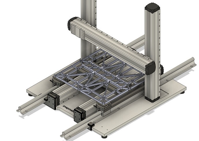
The final design successfully integrates linear guides while preserving the quick swap functionality and adding adjustability. An initial concept involving a clamping lever was discarded for simplicity, resulting in a more streamlined and effective system.
Figure 1: Assembly overview of the linear guide system.
Connecting the Bearing Blocks
A crucial aspect of the design is ensuring the bearing blocks remain aligned and at a consistent distance from the Y-axis motors, especially when swapping between different modules. This prevents the blocks from shifting and ensures consistent performance. Initially, a 2020 aluminum profile was considered for connecting the bearing blocks, but height constraints became apparent. A slimmer 2010 profile was also deemed potentially too shallow.
Figure 2: Connecting bearing blocks using printed angle brackets for stability.
The solution was to design and print angle brackets with slotted holes. Alternatively, similar angles can be sourced from hardware stores. One angle bracket incorporates a riser to connect to each of the Y-axis motors. When printing these brackets, diagonal orientation on the print bed is recommended to ensure they fit within the reduced print area caused by the quick swap kit.
Files: Far side runner.stl Linear rail runner V2.stl
Adjustable Rail Connector
The adjustable connector design is heavily inspired by brvdboss’s system but modified for quick swap compatibility. Instead of enclosing the frame within a part, this design utilizes the unused M5 threads on the 3D printing heated bed, a consequence of the quick swap kit. A flat surface with screw holes attaches to the bottom of the frame. CNC bed compatibility is planned for future iterations.
Figure 3: Assembly of the adjustable connector, allowing for height adjustments.
To simplify printing, an M20 thread with a 2.5mm pitch was designed using Fusion360’s built-in thread tool. The thread length is designed to be sufficient for most setups but can be adjusted if needed. This connector is intended to be permanently attached to each bed type (3D printing, CNC, laser), ensuring consistent leveling settings for each module.
Figure 4: Top detail of the adjustable connector showing the printed thread.
Files: Top with Thread V4.stl
Clamp
The clamp component attaches to the bearing blocks via the previously installed angle brackets. It features recesses for countersunk screws to ensure smooth sliding of the nut component.
Figure 5: Bearing block clamp securely holding the nut component.
Files: Clamp without hebel V3.stl
The Nut
The nut, also inspired by brvdboss’s adjustable system, is designed to mate with the M20 thread of the top connector. It features a 45mm base that slides into the clamp and incorporates holes for optional M3 grub screws.
Figure 6: Nut component seated in the clamp, enabling vertical adjustment.
The nut is intended to be fixed to the “top with thread” part. Once bed leveling is completed, grub screws can be used to lock the nut in place. This allows for consistent bed leveling even after removing and reinstalling the bed, minimizing the need for repeated calibration. The clamp design might slightly restrict nut rotation, but this was deemed a necessary trade-off to maximize the adjustment range without increasing the nut’s height.
Files: Nut V3.stl
Conclusion: Enhanced Stability and Precision with Linear Guides
Implementing this linear guide upgrade results in a significant reduction in bed level deviation and a noticeable increase in overall stability for the Snapmaker 2.0. While the initial bed leveling process with adjustable nuts requires some patience and iterative adjustments, the improved print quality and CNC performance are well worth the effort. This DIY linear guide modification offers a robust and cost-effective way to enhance the capabilities of your Snapmaker 2.0, particularly for users seeking improved precision and reliability across 3D printing and CNC applications.