Navigating Tier 5 in Satisfactory introduces complexities, particularly with byproducts in oil refining. This quick reference guide provides efficient recipe charts and setup examples to streamline your plastic, rubber, and aluminum production. It’s crucial to separate power infrastructure from production lines, especially with oil byproducts, which can complicate power generation scaling. Dedicate separate resource nodes for power to maintain stable production.
Oil Processing: Plastic and Rubber
Basic Oil to Plastic/Rubber Setup
For a foundational plastic and rubber production, a 600 oil input can yield 200 plastic and 200 rubber. This initial setup might suffice for early Tier 5 progression and can operate with Mk3 belts, although Mk4 belts will eventually be necessary for full capacity.
Starting small and expanding strategically is key, especially considering the early game logistical challenges of transporting oil from distant nodes before train infrastructure is established. Planning your final layout in advance minimizes disruptive dismantling and rebuilding phases as your production needs grow.
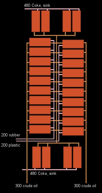
The recommended expandable layout involves parallel rows of refineries – one for plastic and another for rubber – positioned face-to-face. Heavy Oil Residue, a byproduct, is directed to a central shared pipe, which is then processed in refineries at the ends of the rows to produce Petroleum Coke. This coke can be initially sunk for disposal or reserved for later aluminum production. Plastic and rubber outputs are routed along the corridor between the refinery rows. Oil input is fed from the outer ends of the system.
A starting configuration might utilize four refineries. As demand for plastic or rubber increases, simply add more refineries to the respective rows, ensuring sufficient Petroleum Coke refineries are in place to manage the byproduct. Sinks might be needed initially to dispose of excess Petroleum Coke efficiently.
This 600 oil to 200 plastic and 200 rubber setup is tileable for larger scale production. However, by the time such large quantities are required, alternative recipes and more efficient oil processing methods are often unlocked through Hard Drive research, potentially making such extensive tiling unnecessary unless research options are unfavorable.
Aluminum Scrap Production (Update 3 Era)
Basic Bauxite to Aluminum Scrap Setup
This section references the Aluminum processing methods from Update 3 of Satisfactory, which differs significantly from later updates. While outdated, understanding this setup can illustrate byproduct management and resource loop concepts using junction prioritization.
In Update 3, a unit processing 210 bauxite, 240 water, and 60 petroleum coke yielded 360 aluminum scrap and 60 silica. While silica is crucial for later aluminum ingot production, this section focuses solely on aluminum scrap generation.
The diagram shows a doubled configuration of the ratio described above, capable of saturating a Mk5 belt with aluminum scrap output. This design can be further tiled, limited only by the parallel input capacity for bauxite and petroleum coke.
The core design involves a loop of three Alumina Solution refineries fed with 240 water and 210 bauxite. The solution is then pumped upwards to an Aluminum Scrap refinery positioned 8 meters higher and facing the opposite direction.
The 8-meter height difference is critical. It ensures that wastewater from the Aluminum Scrap process prioritizes returning to the Alumina Solution refineries over fresh water input, even though theoretically, overflow should not occur. This height also remains within the Alumina Solution refinery’s natural head lift, eliminating the need for additional pumps, especially if the refineries are built near sea level to minimize water extractor pump requirements. Directing wastewater return opposite to the fresh water input reduces potential pipe throughput and junction priority issues.
In this setup, the petroleum coke input line is routed beneath the Aluminum Scrap refineries, effectively utilizing the available vertical space.
An additional junction at the top level provides an overflow option for excess water, allowing for water packaging and sinking if needed. In practice, with a continuously running production line, water overflow issues are rare with this elevated setup.