Installing a trailer hitch on your Mustang Mach-E opens up a world of possibilities, from hauling bikes to carrying extra cargo for road trips. If you’ve already installed a hitch, or are planning to, the next essential step is wiring your vehicle for trailer lights. This comprehensive Trailer Wiring Guide will walk you through the process, ensuring your trailer lights function correctly and keep you safe on the road. We’ll be focusing on a DIY approach, similar to the popular TorkLift central hitch installation, providing you with the knowledge and confidence to complete this project yourself.
Before we dive in, it’s important to note that this guide is for informational purposes only. While we aim for accuracy and clarity, trailer wiring can be complex, and working with your vehicle’s electrical system should be done with caution.
DISCLAIMER: This guide is intended for informational purposes only. No guarantees are provided regarding safety, accuracy, or optimal procedures. Improper wiring can damage your vehicle, cause personal injury, or void your vehicle’s warranty. Follow this guide at your own risk.
Part 1: Preparing Your Mustang Mach-E for Wiring
Before you start splicing wires, you’ll need to access the necessary areas of your Mach-E’s trunk and identify the taillight wiring. This section will guide you through safely disassembling the trunk interior to gain access.
1.1 Trunk Area Disassembly
To begin, clear out your Mustang Mach-E’s trunk completely. Remove any floor mats, the floorboard covering the spare tire compartment (or tire pump area), and any items you typically store in the trunk, including portable EVSE chargers. This will give you ample space to work.
Next, remove the foam insert that sits within the trunk well.
Step-by-step foam insert removal:
A. Remove Retainer Clips: Locate the two plastic retainer screws/clips securing the foam insert. These are typically found on the top edge of the insert. Use a flat-blade screwdriver to gently rotate these clips counter-clockwise. This will loosen them, allowing for easy removal. Store these clips safely to prevent loss.
B. Open Plastic Flap and Remove Torx Screw: Find the small plastic flap located near the trunk opening on the same trim piece where you removed the clips. Using a flat blade screwdriver or plastic pry tool, carefully pop open this flap. Pry from the side closest to the hatch opening; it’s hinged at the back. Beneath the flap, you’ll find a Torx 25 screw. Use a T25 bit or screwdriver to remove this screw. Keep the clip assembly and screw with the other removed parts. Repeat for any additional clips of this type.
C. Remove Inner Trunk Screws: On the inside edge of the trunk, on the same trim piece where you removed the clips, you’ll find two more screws. These are typically 8mm screws. Use an 8mm socket to remove them and place them in your safe storage location.
D. Detach Plastic Trim Panel: The plastic trim panel is now held in place by several clips. Apply upward force to the trim panel to release these clips. Knowing the approximate location of these clips (usually along the edges and corners of the panel) helps you apply pressure in the right areas.
E. Passenger-Side Trim Panel Access: We need to access the wiring behind the passenger-side trim panel. You don’t need to fully remove it, but pulling it back will provide enough working space. Use a plastic pry tool to gently work under the rubber seal around the hatch opening. Pry the plastic panel away from the car body, close to the clip locations. Focus on prying near the yellow plastic clips, often found just above the black circle-shaped clip locations. These yellow clips sometimes have a notch at the top that can aid in prying. Image 1-4 and 1-5 below illustrate clip locations.
If your Mach-E is equipped with a 12V accessory plug in the trunk, you’ll need to disconnect it. Locate the gray connector for the 12V plug (Image 1-5, circle 9). On the bottom of this connector, there should be a tab. Press this tab to release the latch and firmly pull the gray plug away from the yellow receptacle.
F. Driver-Side Trim Panel Access: Repeat step E for the driver-side trim panel. The clip locations are mirrored on this side.
By following these steps, you’ll have sufficient access to the wiring and grommets needed for running your trailer wiring.
Image 1-3: Diagram illustrating the clip positions and matching holes on the rear hatch trim panel of the Mach-E, aiding in safe removal for trailer wiring access.
Image 1-5: Illustration of the subsequent six clip positions on the passenger-side trunk panel, along with the 12V accessory plug location, crucial for trailer wiring setup.
Image 1-8: An interior view of the passenger-side hatch area with the panel pulled back, revealing the space where the amplifier and subwoofer might be located, relevant to trailer wiring considerations.
Part 2: Mounting the Trailer Wiring Converter and Running the Pigtail
With the trunk panels loosened, you can now prepare for mounting the trailer light wiring converter and routing the trailer connector pigtail to the exterior of your Mach-E.
2.1 Converter Box Placement and Grounding
You have flexibility in choosing which side of the vehicle to mount the trailer wiring converter box. Both sides offer suitable grounding points. While the passenger side has the 12V accessory receptacle, which might seem convenient for power, the driver’s side might be more practical due to grommet proximity for the pigtail.
For this guide, we’ll mount the converter box on the driver’s side.
Mounting and Grounding Steps:
H. Converter Box Location: Identify a suitable location on the driver’s side inner panel to mount the converter box. You might find a screw hole that can be used for mounting. Alternatively, secure it using zip-ties to existing clips or wiring harnesses. Image 2-1, circle 1 shows a possible location.
I. Grounding: Locate a bolt near your chosen mounting location for grounding. Remove the nut from the bolt (Image 2-1, circle 2). Attach the negative/ground wire from your converter box to this bolt and reattach the nut securely. An 8mm socket is commonly used for these bolts.
2.2 Running the Trailer Connector Pigtail
To connect your trailer lights to the wiring, you’ll need to run the 4-wire pigtail from inside the trunk to the trailer hitch area underneath the car.
J. Locate Trunk Grommet: With the side panels loosened and carpeting lifted, you’ll find rubber grommets providing access to the underside of the Mach-E. Locate a grommet large enough to pass the connector end of your trailer wiring pigtail through. A grommet on the driver’s side is often convenient.
K. Grommet Modification and Pigtail Routing: Carefully remove the grommet. Create a notch or an “X” shaped slit in the grommet to allow the pigtail wires to pass through. Avoid cutting the outer lip of the grommet if possible. Feed the connector end of the pigtail through the modified grommet from inside the trunk to the underside of the car. Re-insert the grommet around the wire to maintain a seal. Image 2-2 shows the grommet location from underneath the vehicle.
L. Pigtail Securing: Once the pigtail is routed, secure it to the trailer hitch using zip-ties. Zip-tie it along the hitch frame to prevent it from dangling or rubbing against vehicle components over time. Image 2-3 shows the pigtail secured to the hitch.
Note: Accessing the underside grommet usually requires removing the undercarriage protector. If you’ve already removed it for hitch installation, this step is simplified. However, for pigtail routing alone, you might only need to remove a smaller access panel, secured by a few bolts, instead of the entire undercarriage protector.
Part 3: Connecting to Power and Taillight Wiring
This is where precision and careful work are crucial. You will be tapping into your Mustang Mach-E’s electrical system to power the trailer lights.
3.1 Identifying Taillight and Power Wires
Before making any connections, it’s essential to identify the correct wires for each trailer light function (left turn, right turn, taillights, brake lights) and a 12V power source. Using a multimeter is highly recommended for this step.
Wire Functions:
- Left Turn Signal
- Right Turn Signal
- Taillights (Running Lights)
- Brake Lights
- 12V Power
Taillight Wire Access:
M. Remove LED Light Enclosures: Access the LED taillight modules by removing the plastic caps (two per side) located under the tailgate opening. Use a pry tool or small screwdriver to carefully pop these caps off. Images 3-4 and 3-5 show cap removal.
N. Remove Screws: Underneath the removed caps, you’ll find 8mm screws (two per side). Remove these screws.
O. Detach Light Enclosures: Carefully pull the LED light enclosure outward to disengage it from the pressure fittings. Using a plastic pry tool on the outer edge of the enclosure while pulling from the opposite side can be helpful. Images 3-6 and 3-7 illustrate this.
P. Disconnect Light Module Plug: While holding the LED enclosure, locate the 8-pin connector plug. Depress the plastic latch on the plug (facing the rear bumper) and firmly pull the plug to disconnect it from the receptacle. Repeat for both sides.
Q. Locate Wire Grommets: Above the pressure fittings, you’ll find small rubber grommets on the car body. Remove these grommets from both sides. You’ll need to slit these grommets to pass the trailer wiring tap wires through. Image 3-8 shows the grommet location.
3.2 Wire Tapping and Connections
R. Identify Wire Pinouts: Refer to Image 3-2 and Table 3-3 for the pinouts of the LED light module plugs. Use a multimeter to verify these pinouts on your specific Mach-E model, as wire colors can sometimes vary.
S. Prepare Tap Wires: Cut lengths of wire (matching the gauge of your trailer wiring module) long enough to reach from the taillight area to your chosen converter box location.
T. Wire Tapping Method: Standard “blue wire taps” may not reliably pierce the insulation of the wires on the LED enclosure pigtails, as these wires can be quite thin. A more robust method is to carefully strip a small section (about 1/2 inch) of insulation from the identified wires on the LED pigtail, a few inches away from the plug. Twist the end of your tap wire around this exposed section of wire. Solder the connection to ensure a solid and lasting electrical contact. Image 3-10 demonstrates this soldering technique. After soldering, allow to cool, trim excess wire, and insulate the connection thoroughly with electrical tape.
Important Notes on Wire Tapping:
- Wire Length: Ensure your tap wires are long enough to reach the trailer wiring converter. If placing the converter on the opposite side, you’ll need extra length.
- Wire Routing: Before soldering, remember to feed the tap wires through the grommets you prepared in step Q and fish them through to the side panel area of the car.
- Alternative Converters: Consider “sensor-based” trailer wiring converters that detect signals without direct wire splicing if you prefer a non-invasive approach.
U. Route Wires and Reassemble Taillights: After soldering and insulating the connections, carefully route the tap wires through the prepared grommets and into the side panel area of the car. Leave some slack in the wires near the taillight housing for easy future removal. Plug the LED light module plugs back into their receptacles. Neatly route the new wires away from the pressure fittings and press the light enclosures back into place. Image 3-12 shows proper wire routing and enclosure reassembly.
V. Repeat for Opposite Side: Repeat steps R-U for the other LED taillight module and side of the car. On the driver’s side, route wires through an opening beyond the amplifier and zip-tie them to existing wire harnesses. Image 3-13 shows driver-side wire routing. On the passenger side, route wires behind the amplifier and secure them to harnesses, avoiding contact with the amplifier itself. Image 3-14 shows passenger-side routing.
W. 12V Power Tap: Locate the purple wire feeding the 12V accessory port in the trunk area (Image 3-15). Use a wire tap (or soldering method if preferred) to connect the 12V power wire from your trailer wiring converter to this purple wire.
X. Final Wiring and Connections: Neatly route and tape the 12V power tap wire along existing power cables and join it with the wires you ran from the taillight modules. Route these wires behind the insulation on the side of the car, leading to the location of your trailer wiring converter. Connect all the tap wires to the appropriate inputs on your trailer wiring converter according to the converter’s instructions. Use zip-ties and electrical tape to secure all wiring, preventing rubbing, shifting, or crimping when panels are reattached. Image 3-17 shows a fully wired harness.
Y. Testing: Before fully reassembling the trunk, connect a trailer or use a trailer light tester to verify all trailer light functions are working correctly: left turn signal, right turn signal, taillights (running lights – ensure headlights are on), and brake lights. Image 3-18 shows a functionality test.
Z. Reassembly: Once testing is successful, begin reassembling the trunk panels and trim pieces in reverse order of disassembly. Use a trim removal tool to help tuck the rubber hatch seal back into place as you reattach panels. Image 3-19 shows seal reattachment.
| Pin # | Function | Wire Color (YMMV) |
|---|---|---|
| 1 | Tail / running light | Brown |
| 2 | Stop Light | Red |
| 3 | Steady 12V | N/C |
| 4 | Turn signal (RT / LT) | (Yellow / Green) |
| 5 | Steady 12V | N/C |
| 6 | Ground ? | N/C |
| 7 | Ground ? | N/C |
| 8 | Ground ? | N/C |

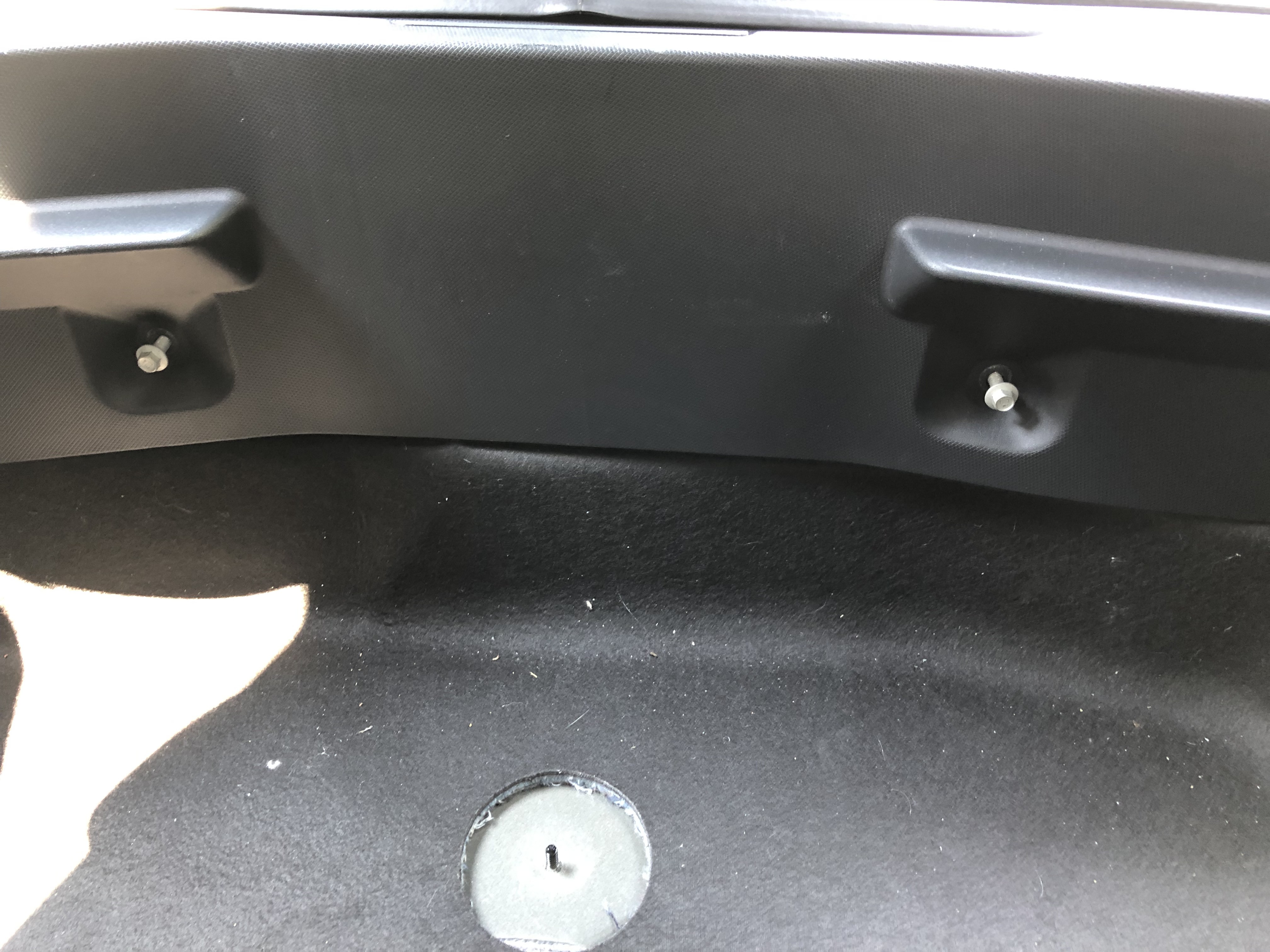
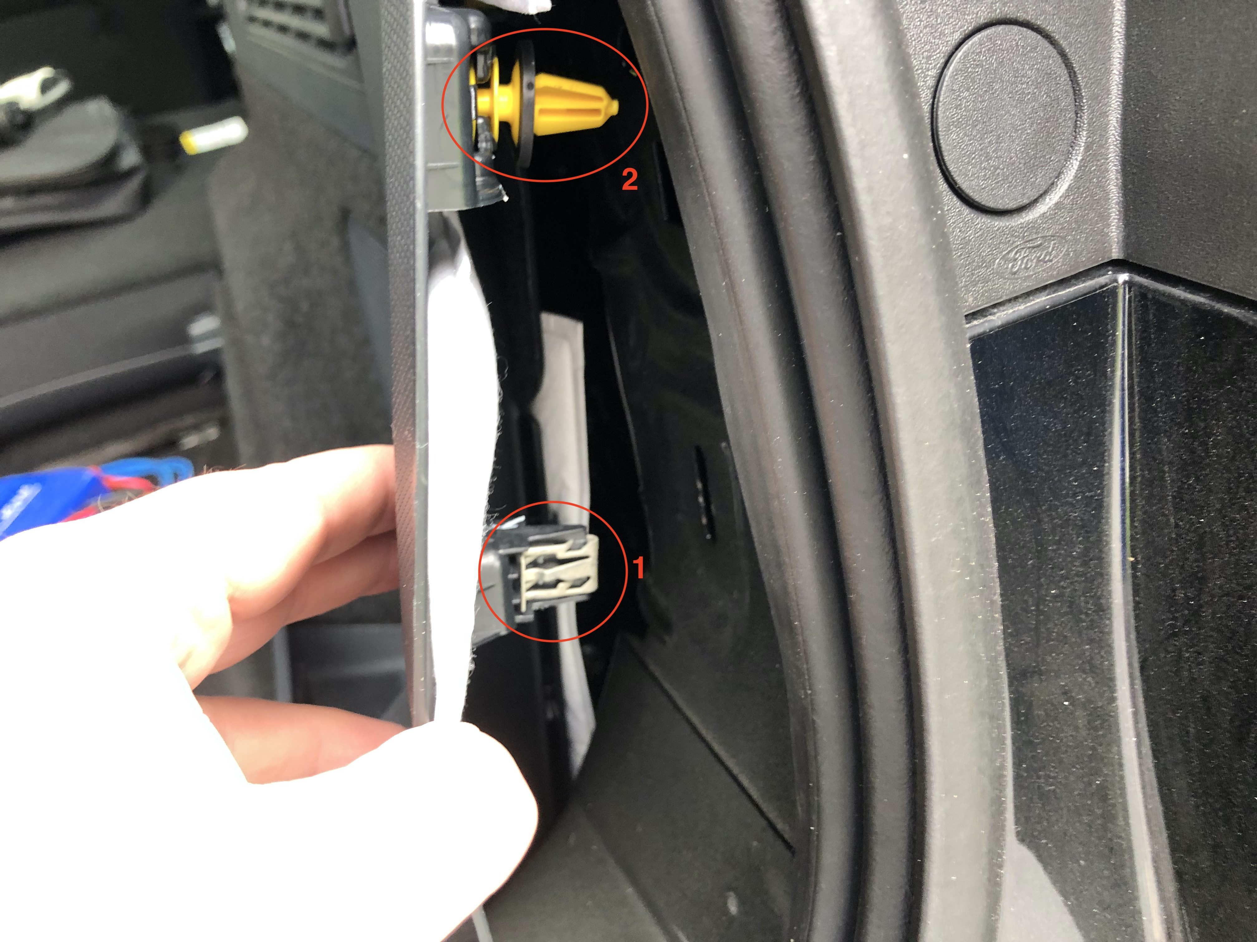
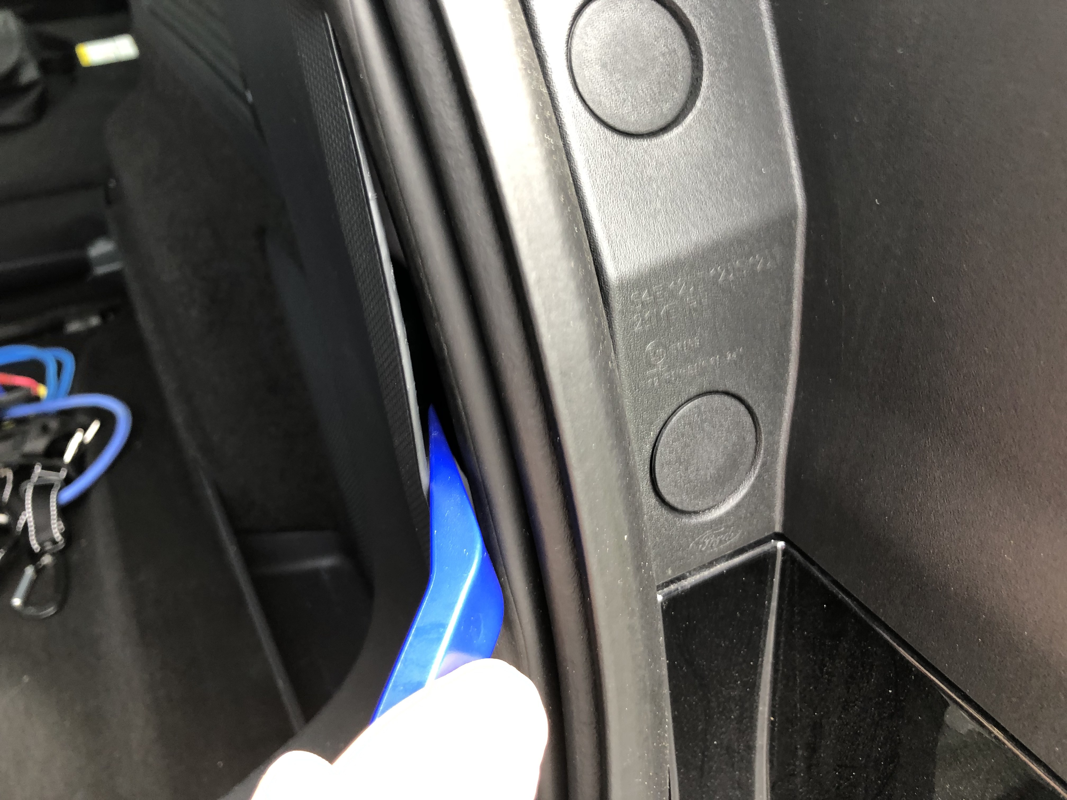
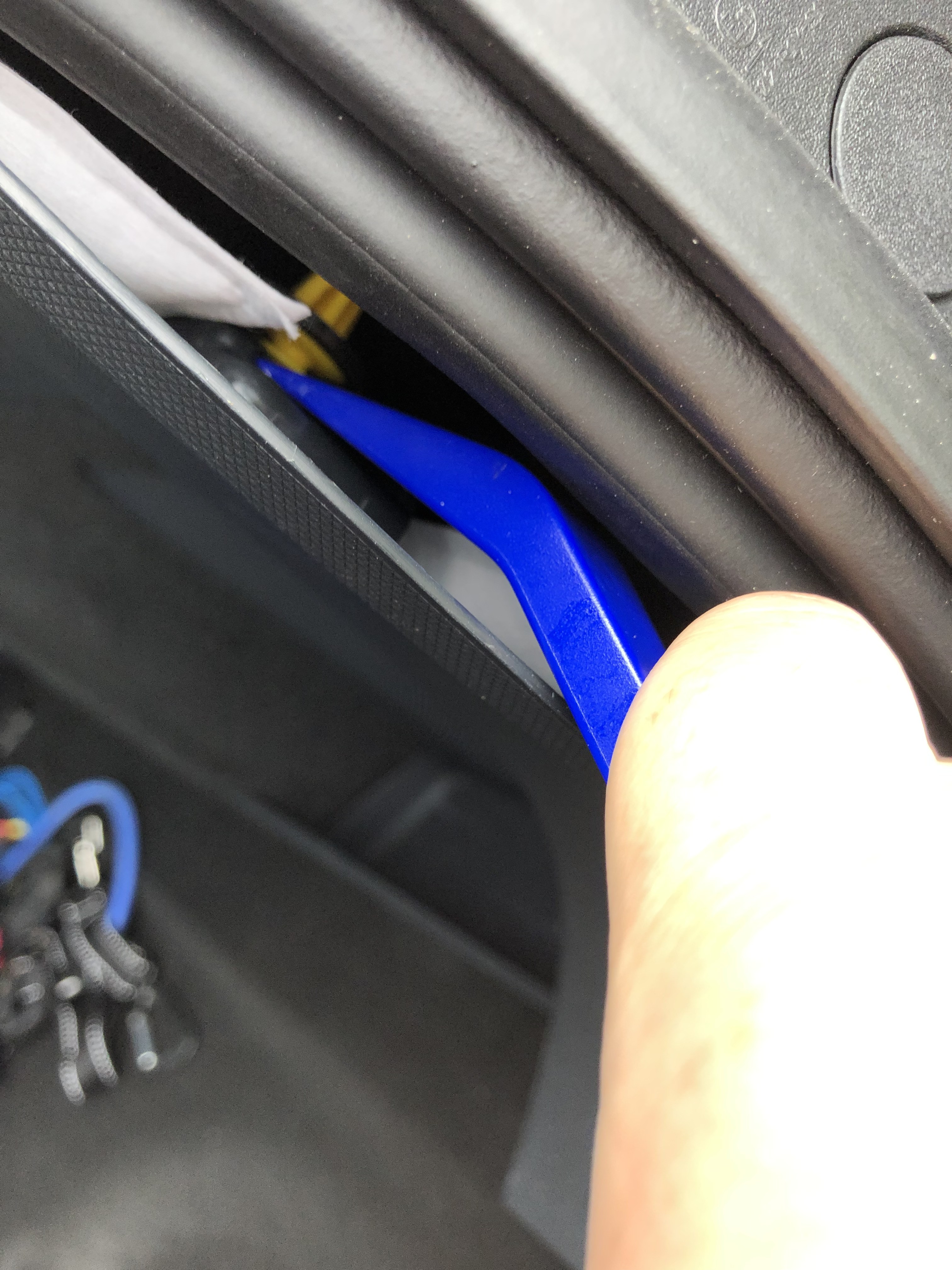
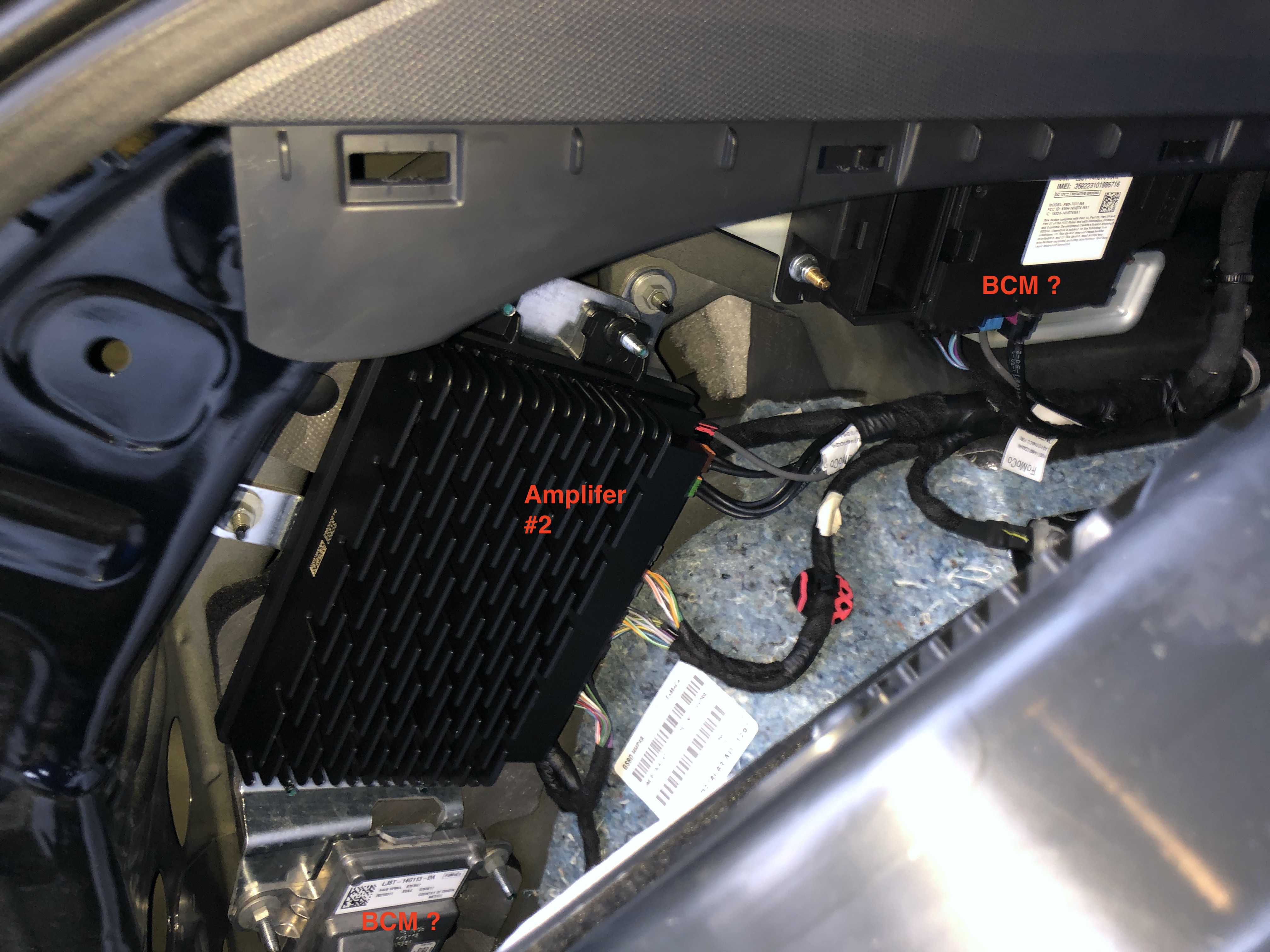
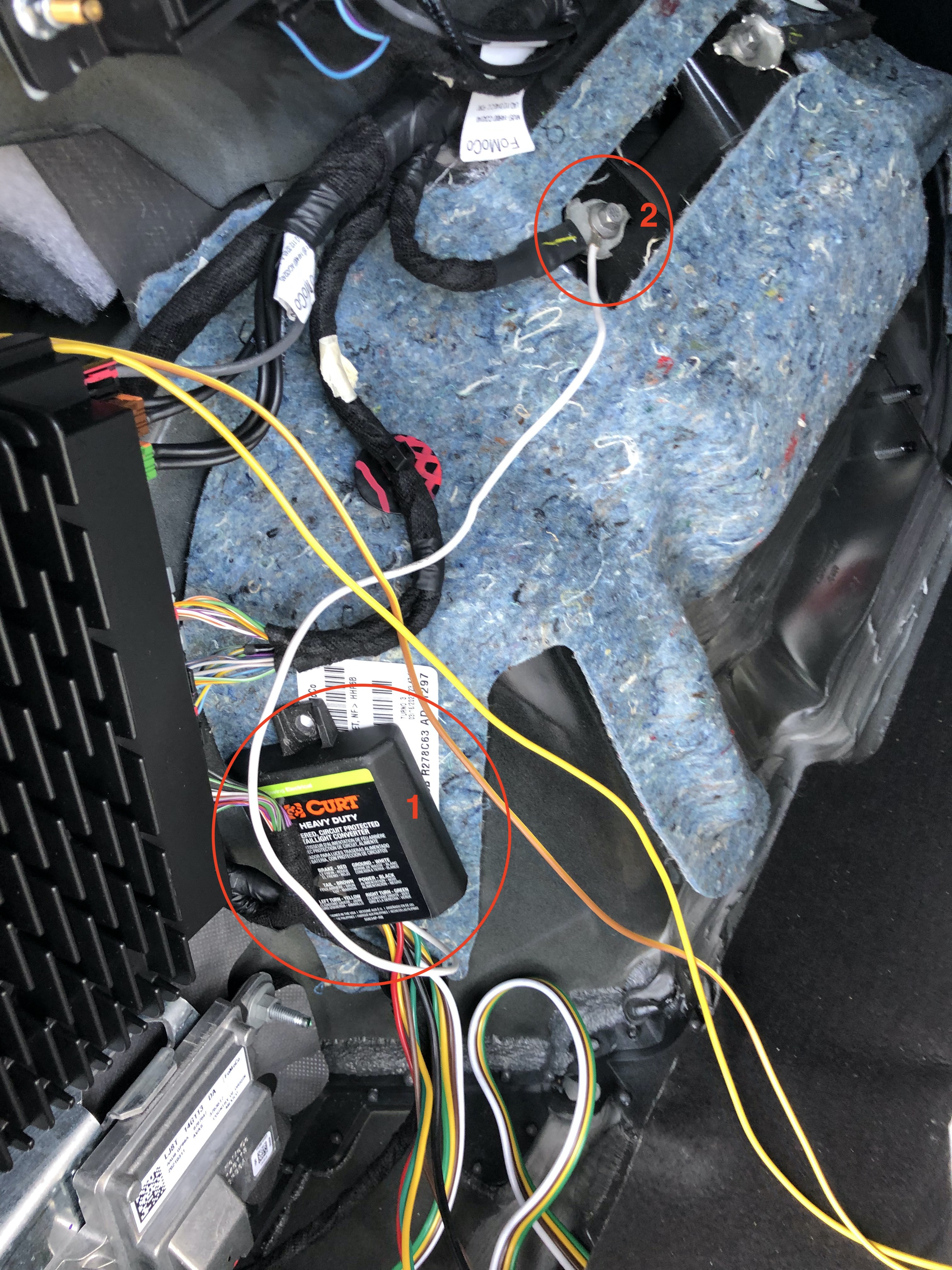
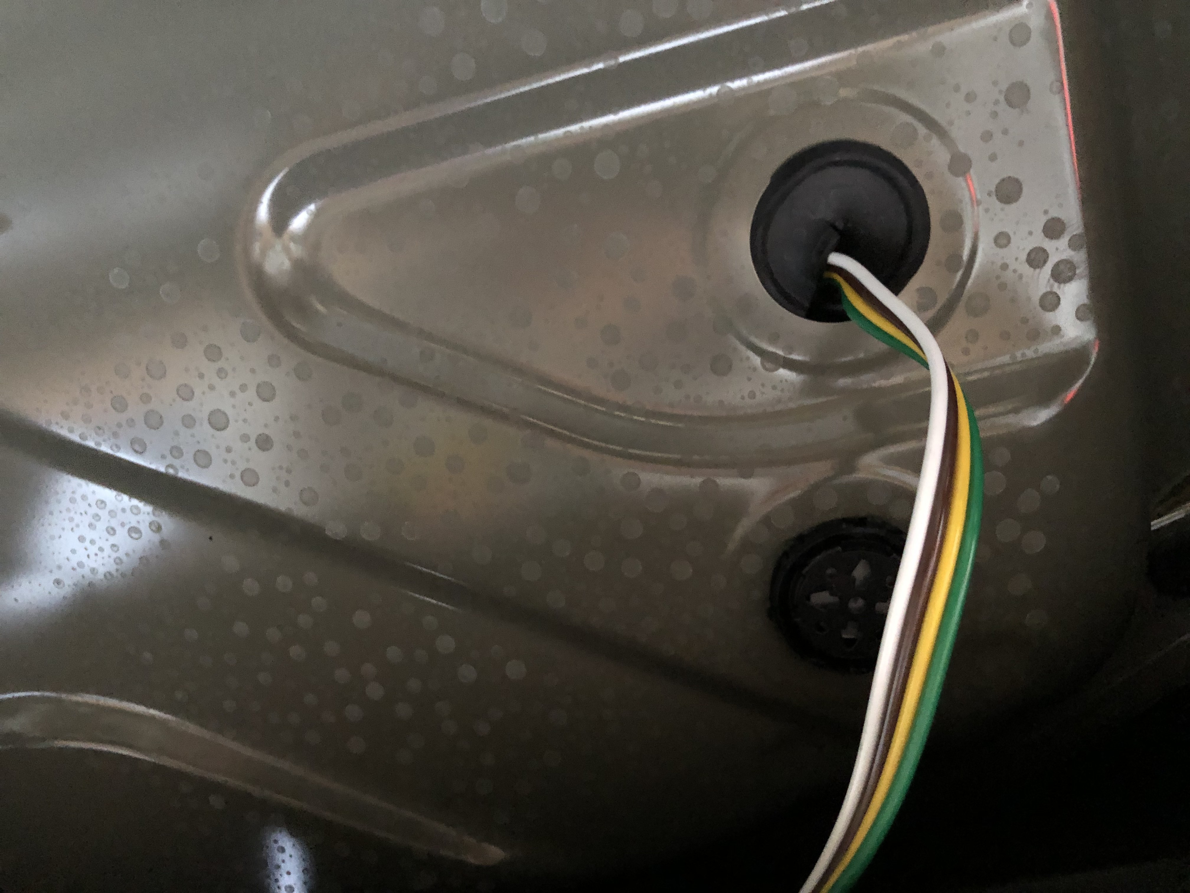
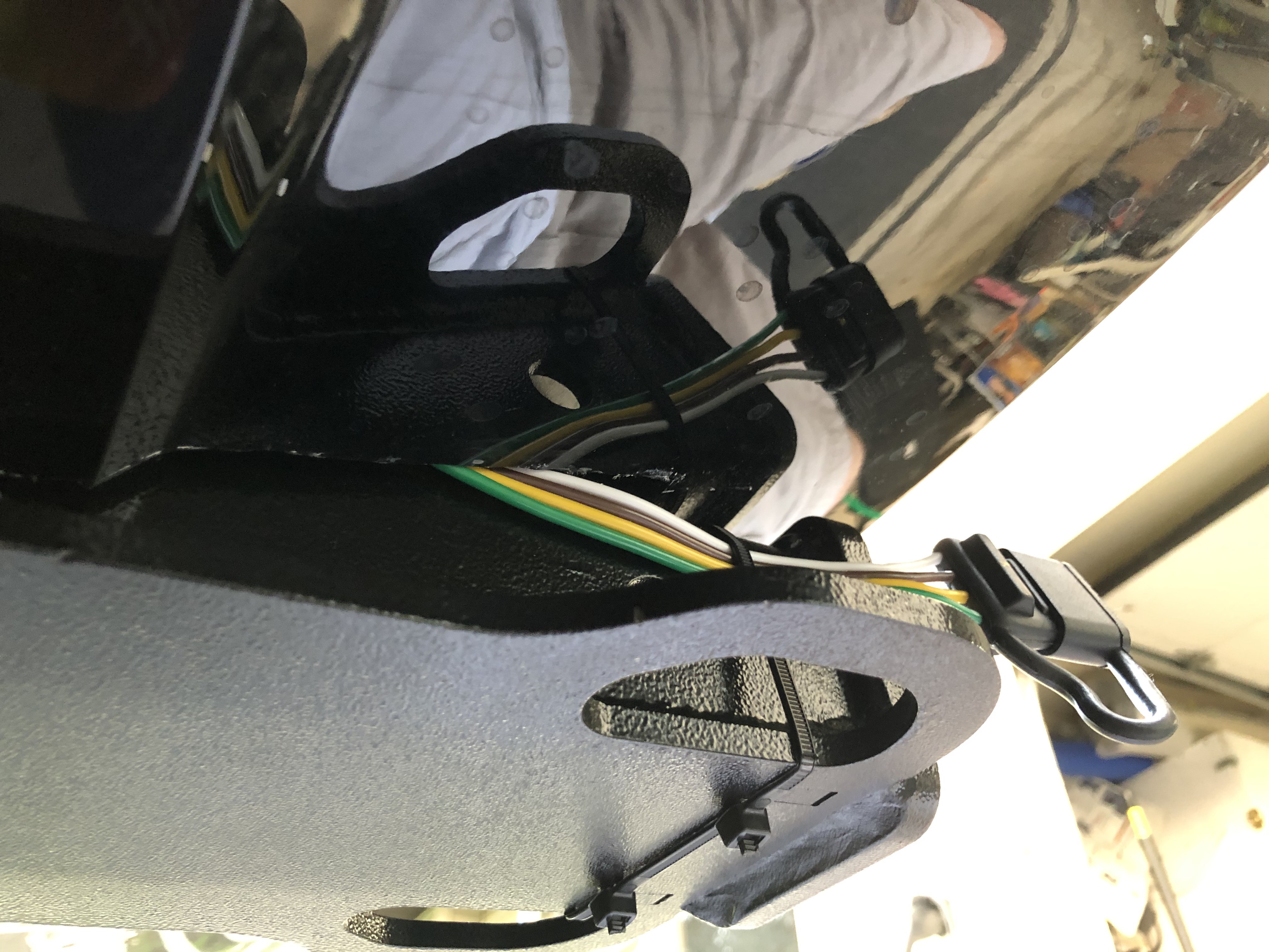
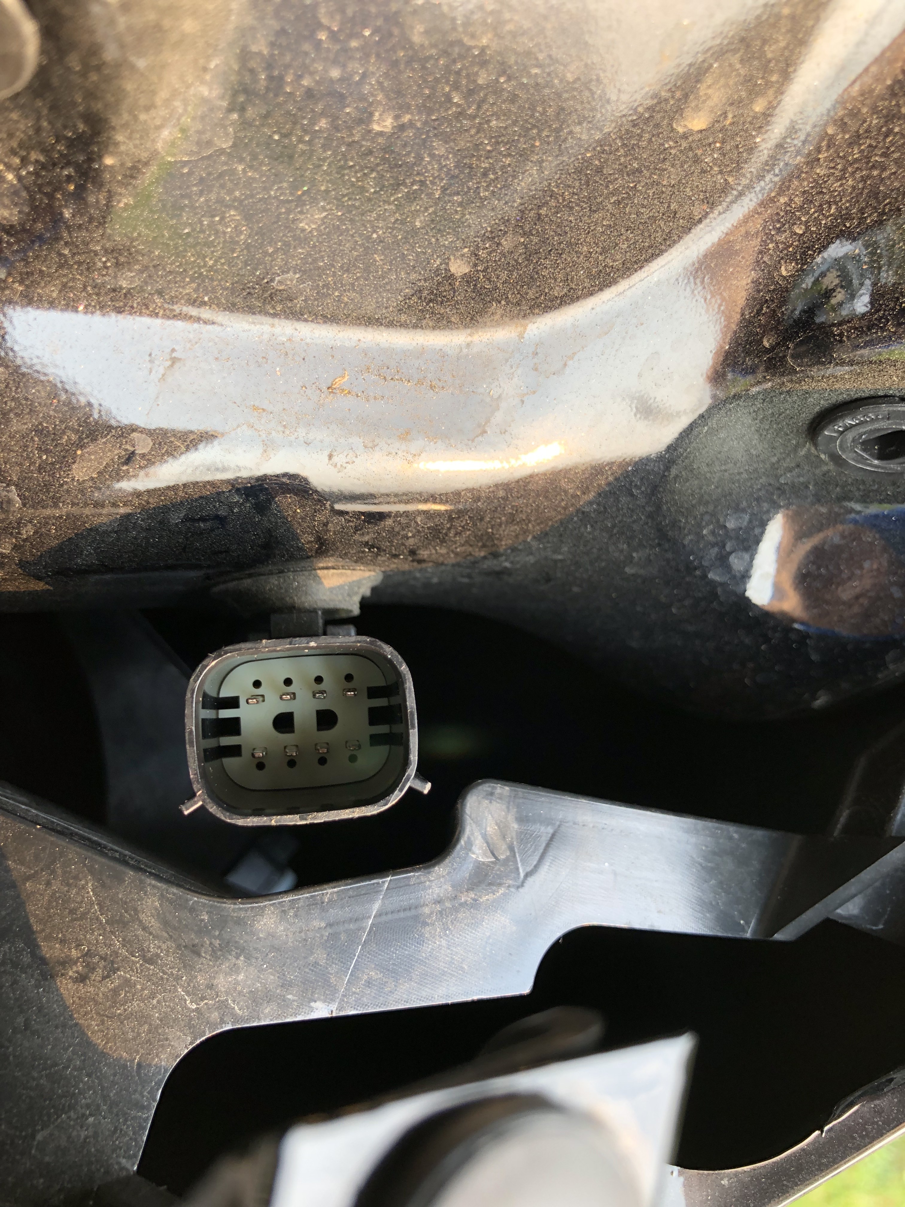
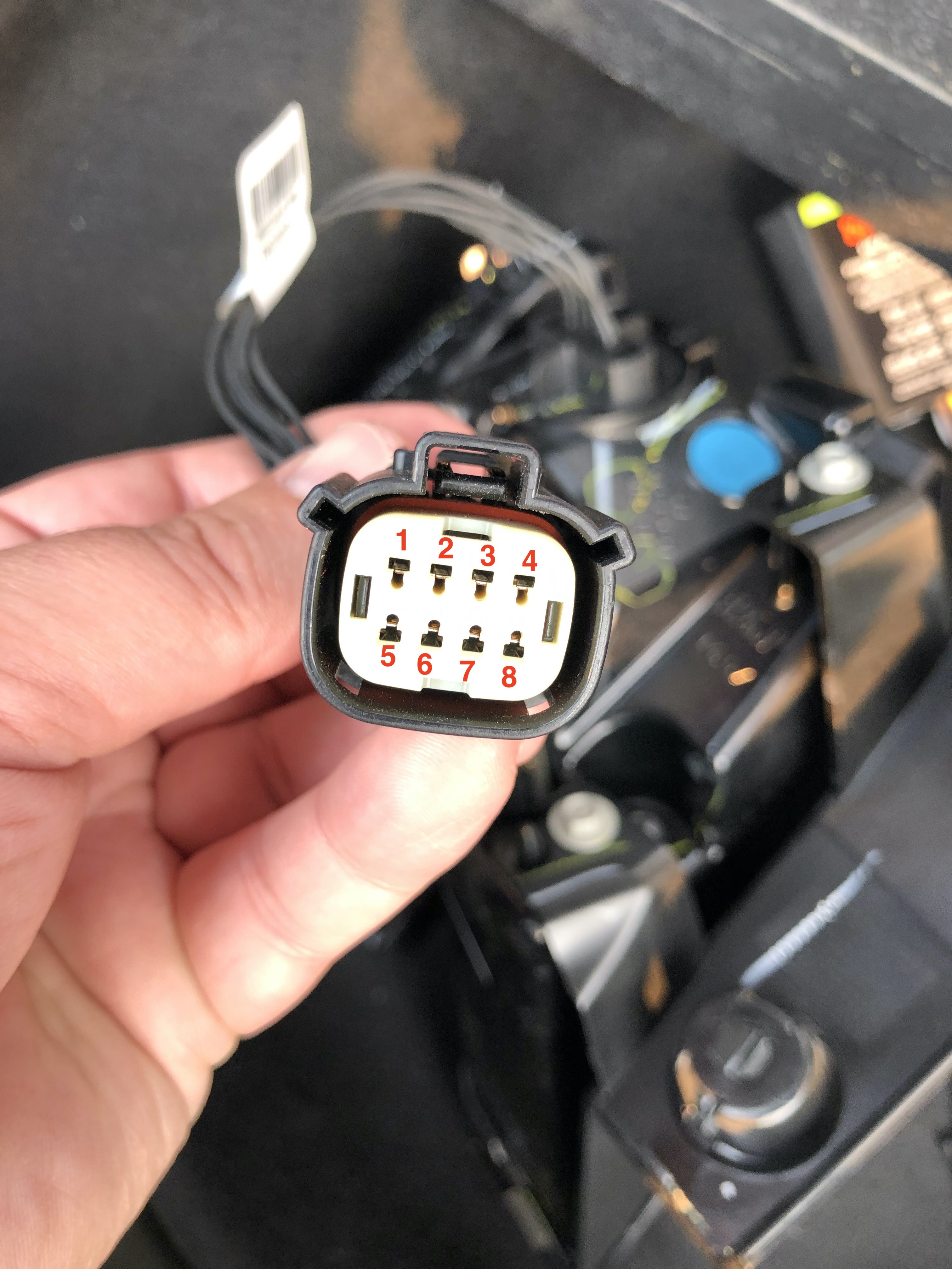
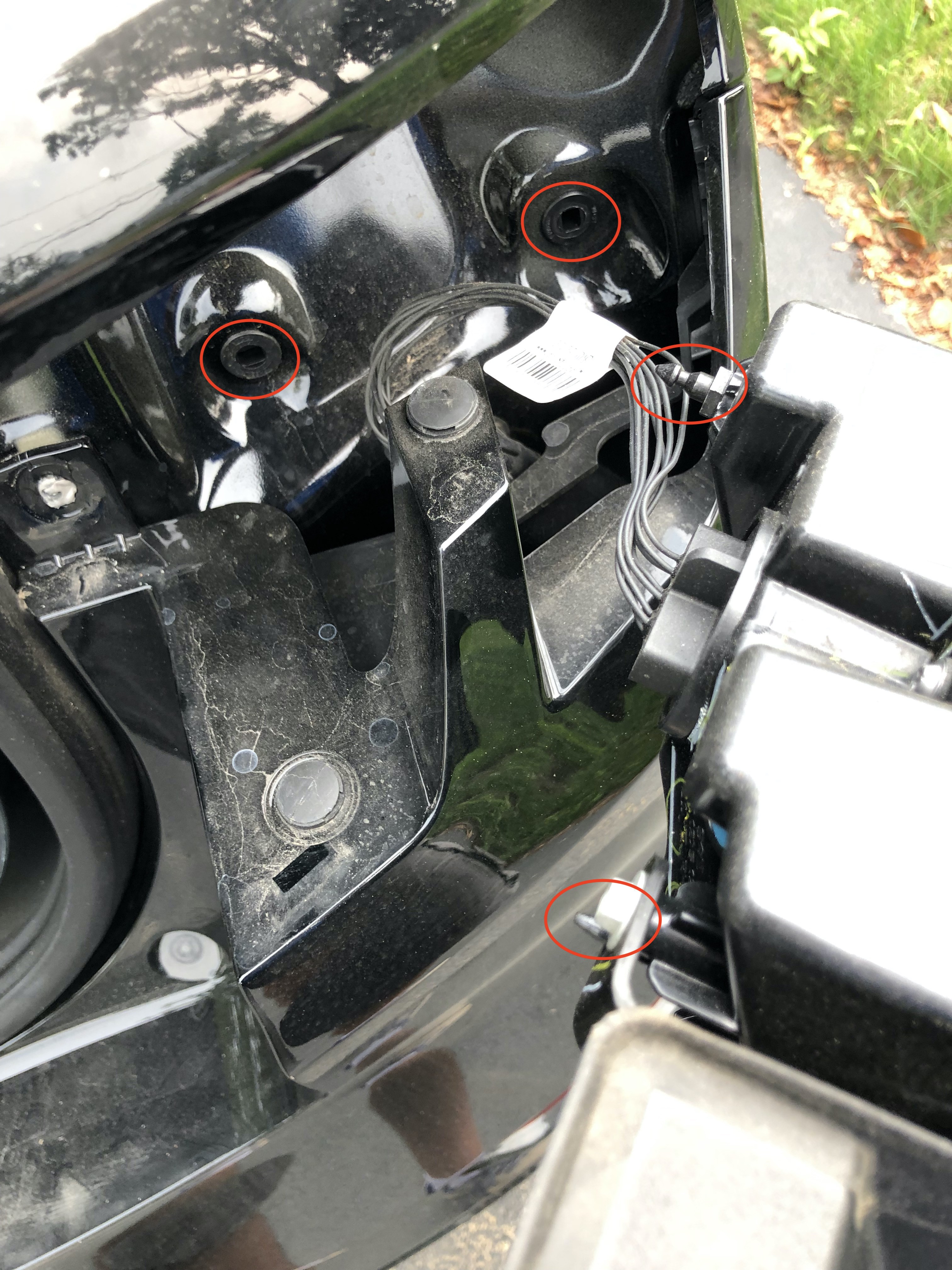
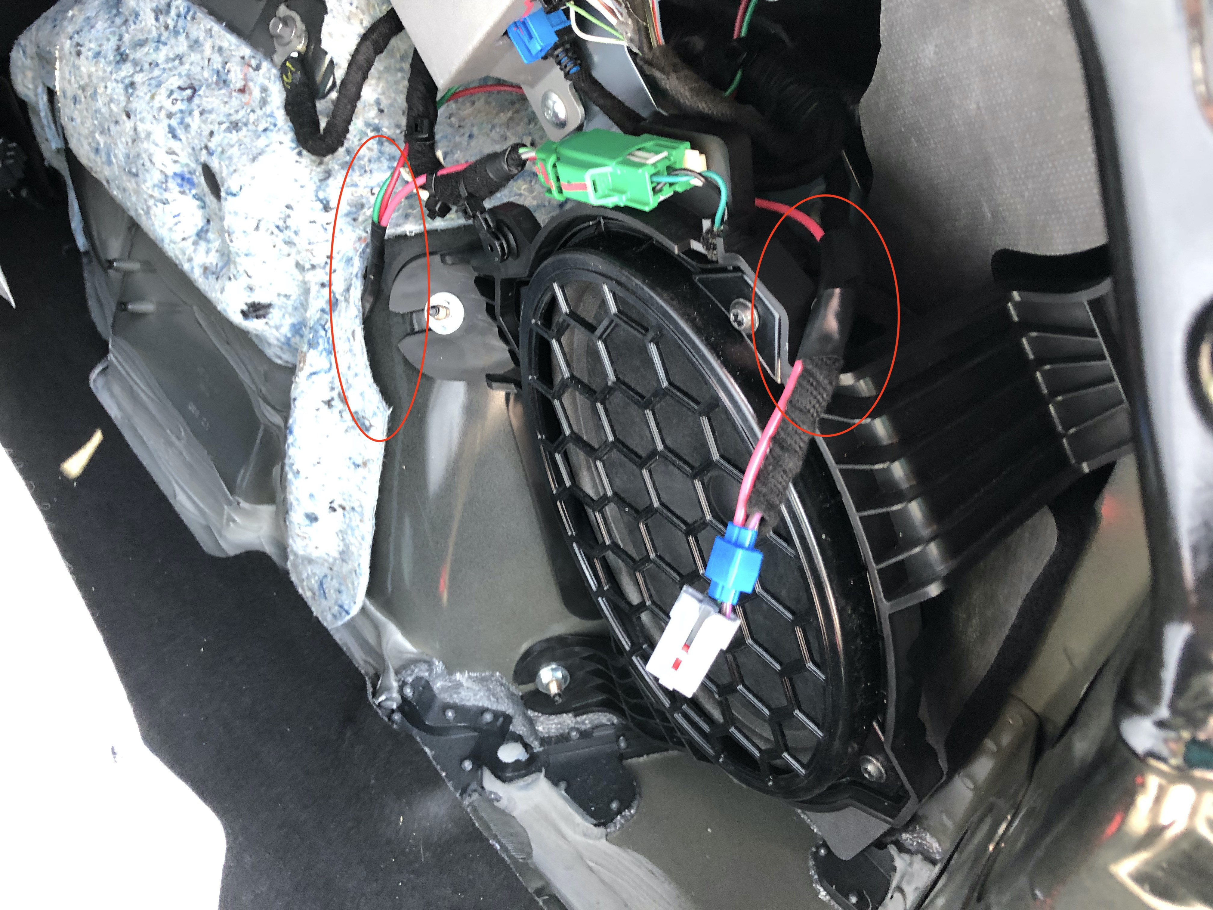
Table 3-3: Pinout mapping for the Mach-E LED light modules, detailing function and potential wire colors to aid in trailer wiring.
Image 3-4: Detail of a removed cap from the Mach-E taillight housing, indicating tab locations for removal and access to mounting screws.
Image 3-5: Demonstration of using a pry tool to remove plastic covers on the Mach-E taillights, revealing screws for accessing LED light wiring.
Image 3-6: Illustrating the process of popping the Mach-E LED enclosure out of its pressure clips, allowing access to the wiring harness.
Image 3-8: Highlighting the rubber grommet on the Mach-E body, used for routing wires from the LED light enclosures into the side panels.
Image 3-9: Detailed view of the passenger-side light enclosure pigtail, showing wire labels for pins 1 and 3, aiding in correct trailer wiring connections.
Image 3-10: Demonstration of tapping wires by exposing the plastic coating and soldering tap wires in place, ensuring a secure connection for trailer lights.
Image 3-11: Showing the process of running wires through the grommet and fishing them into the side panel of the Mach-E, routing trailer wiring effectively.
Image 3-12: Illustrating plugging in the LED enclosure and routing new wires away from pressure fittings, ensuring proper assembly and wire management.
Image 3-13: Demonstrating wire routing from the driver’s side LED wire taps in the Mach-E, showing how to organize and secure the new wiring.
Image 3-14: Showing wire routing from the passenger side LED wire taps in the Mach-E, focusing on neat and secure wiring practices.
Image 3-15: Illustration of tapping into the 12V power source from the accessory port in the Mach-E hatchback, providing power for the trailer wiring system.
Image 3-17: Overview of the fully wired trailer light harness in the Mach-E, showing the completed wiring setup and component placement.
Image 3-18: Emphasizing the importance of testing the newly installed trailer wiring functionality before reassembling the Mach-E’s interior panels.
Image 3-19: Instruction to move the rubber seal out of the way when reattaching panels and trim pieces in the Mach-E, ensuring proper and clean reassembly after trailer wiring.
By following these detailed steps, you should be able to successfully install trailer wiring on your Mustang Mach-E, enabling you to safely tow and enjoy the added utility. Remember to always double-check your connections and test thoroughly before hitting the road.