The Snapmaker 2.0 is a versatile machine, but like many makers, you might be looking for ways to enhance its performance, particularly in 3D printing and CNC operations. One popular and effective upgrade is the implementation of Linear Guide Rails. This article delves into a user-designed linear guide rail system for the Snapmaker 2.0, focusing on its benefits, design considerations, and components. This DIY approach provides a practical solution for makers seeking improved stability and precision without sacrificing the convenience of the Snapmaker’s quick swap system.
Why Integrate Linear Guide Rails into Your Snapmaker 2.0?
Upgrading to linear guide rails offers several key advantages for Snapmaker 2.0 users:
- Eliminate Bed Wobble in 3D Printing: Linear guide rails significantly reduce unwanted bed movement during 3D printing. This stability is crucial for achieving smoother surfaces, sharper details, and overall higher print quality, especially for larger or more complex models.
- Enhanced Stability for CNC Machining: When performing CNC tasks, the added rigidity from linear guide rails is invaluable. It minimizes vibrations and ensures consistent toolpaths, leading to cleaner cuts, improved accuracy, and the ability to work with a wider range of materials.
- Protect Your Bed from Accidental Damage: In the event of a 3D printing sensor malfunction or G-code error, a toolhead crash can severely damage the print bed. Linear guide rails provide extra support and can help to mitigate damage by preventing excessive bed deflection upon impact. This added protection can save you from costly repairs and downtime.
Design Goals for a Snapmaker 2.0 Linear Guide Rail System
When designing a linear guide rail upgrade for the Snapmaker 2.0, several key requirements were considered to ensure functionality and ease of use:
- SBR16 Rail Compatibility: The system is designed to be compatible with readily available SBR16 linear guide rails. This choice balances performance with cost-effectiveness and ease of sourcing components. The design should also be adaptable to other rail types if desired by the community.
- Quick Swap Kit Integration: Maintaining the functionality of the Snapmaker 2.0’s quick swap kit is paramount. The upgrade should not hinder the ability to easily switch between 3D printing, CNC carving, and laser engraving modules.
- Adjustable Height for Bed Warping Correction: Addressing potential bed warping is essential for achieving a level printing surface. The design incorporates height adjustability to compensate for any bed irregularities and ensure consistent first layers.
- Printable Design with Minimal Supports: To facilitate accessibility for DIY makers, the components are designed to be 3D printable with minimal or no support structures, simplifying the fabrication process.
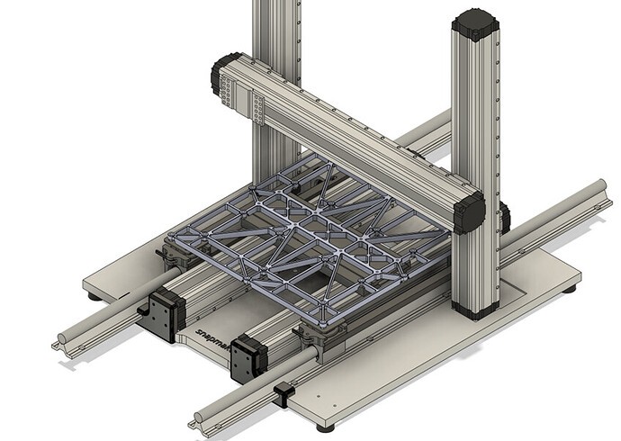
Concept Design: Components Breakdown
This linear guide rail upgrade concept draws inspiration from various community designs and focuses on creating a modular and effective system. Let’s examine the key components:
Connecting the Bearing Blocks
Ensuring the linear guide rail bearing blocks remain correctly positioned and aligned is crucial, especially when utilizing the quick swap system. To achieve this, a connecting element is used to link the bearing blocks at specific distances from the Y-axis prime movers.
Initially, a 2020 aluminum profile was considered for this connection. However, height constraints became apparent. A 2010 profile was then evaluated, but deemed potentially insufficient in height. Ultimately, a custom-designed angle bracket with slotted holes was chosen for its optimal balance of height and functionality. These brackets can be 3D printed or sourced from hardware stores. One angle bracket incorporates a riser to connect to each Y-axis mover.
Alt Text: Exploded view of the DIY linear guide rail system assembly for Snapmaker 2.0, highlighting the relative positions of components.
Alt Text: Close-up of the bearing block connections in the linear rail system, showing the angle brackets and their attachment points.
Files for Bearing Block Connectors:
Adjustable Rail Connector
This component, heavily inspired by existing adjustable linear guide rail designs, is adapted for seamless integration with the Snapmaker 2.0 quick swap system. The key modification is its ability to slide in and out with the quick swap mechanism.
Instead of a frame-fitting design, this connector utilizes the spare M5 threads on the 3D printing heated bed (exposed by the quick swap kit). A flat surface with screw holes allows direct attachment to the bed frame. CNC bed compatibility is planned for future iterations.
Alt Text: Detailed assembly diagram of the adjustable rail connector, illustrating how the threaded top piece and clamp interact.
Alt Text: 3D model rendering of the adjustable connector’s top piece with integrated M20 thread, designed for 3D printing.
The connector features a 3D-printable M20 thread with a 2.5mm pitch, designed using Fusion360’s thread functionality. While the thread length may be subject to adjustment, initial testing indicates it is suitable for most installations. This component is intended to be permanently fixed to each interchangeable bed (3D printing, CNC, laser).
File for Adjustable Rail Connector Top:
Clamp
The clamp component secures to the bearing blocks (via the angle brackets) and accommodates the sliding adjustable rail connector. Countersunk screw holes are incorporated to ensure smooth sliding action without obstruction.
Alt Text: Image of the 3D printed clamp designed to secure the bearing blocks of the linear guide rail system, showing screw hole details.
File for Clamp:
Nut
Mirroring the adjustable system inspiration, a nut component is designed to mate with the M20 thread on the adjustable connector top. The nut features a 45mm base that slides into the clamp. M3 screw holes are included to allow for locking the nut in place after bed leveling.
Alt Text: Illustration of the nut component positioned within the clamp, demonstrating the sliding base and locking screw holes.
The intention is to fix this nut to the “top with thread” component. Once bed leveling is achieved, the nut can be locked, theoretically preserving the level setting even after bed removal and reinstallation. Rotation of the nut within the clamp might present a minor challenge, but the design prioritizes maximum adjustment range by maintaining a compact nut height.
File for Nut:
Conclusion: Enhanced Stability and Precision
Implementing this DIY linear guide rail upgrade on a Snapmaker 2.0 demonstrably improves bed stability and printing precision. While the bed leveling process may require some initial adjustments and iterations of leveling, adjusting the nuts, and re-leveling, the resulting reduction in bed level delta and increased overall stability are well worth the effort. This upgrade provides a significant enhancement for both 3D printing and CNC capabilities of the Snapmaker 2.0, empowering makers to achieve higher quality results.